Aircraft landing surveillance guiding method

A technology of aircraft and monitor, applied in the direction of landing auxiliary equipment, etc., can solve the problems of fixed parameters, immobility, and affecting flight safety, etc., and achieve the effect of expensive equipment, convenient disassembly and assembly, and simple maintenance

Active Publication Date: 2017-06-06
NAVAL AVIATION UNIV
View PDF6 Cites 6 Cited by
  • Summary
  • Abstract
  • Description
  • Claims
  • Application Information

AI Technical Summary

Problems solved by technology

[0003] There are three problems with the installation of the centerline camera: first, the new airport needs to be pre-installed and cannot be moved; second, the relevant parameters are fixed and cannot be adjusted flexibly; flight safety

Method used


Image

  • Aircraft landing surveillance guiding method
  • Aircraft landing surveillance guiding method
  • Aircraft landing surveillance guiding method

Examples


Embodiment

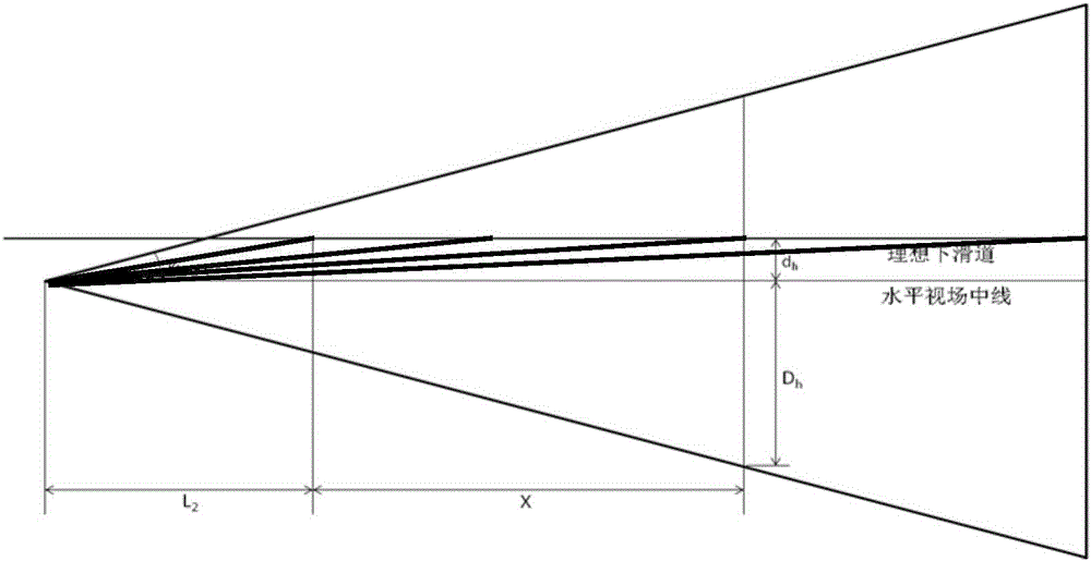
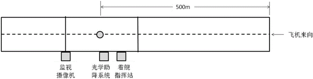
[0024] Embodiment: the landing glide path is usually from the ideal landing point to the aircraft 1 and extends 1800 meters to be the ideal glide line far-end projection point. In the monitor 3, the aircraft 1 is required to be able to determine the position of the aircraft 1 at the ideal glide line far end and Attitude, the main part of the aircraft 1 body can be displayed at the near end of the ideal landing point; it can work normally within the range of conventional ambient light changes; it does not need to be sensitive to color; therefore select the black and white camera 6, and the lens selects a fixed focus with an angle of view of 8° lens.

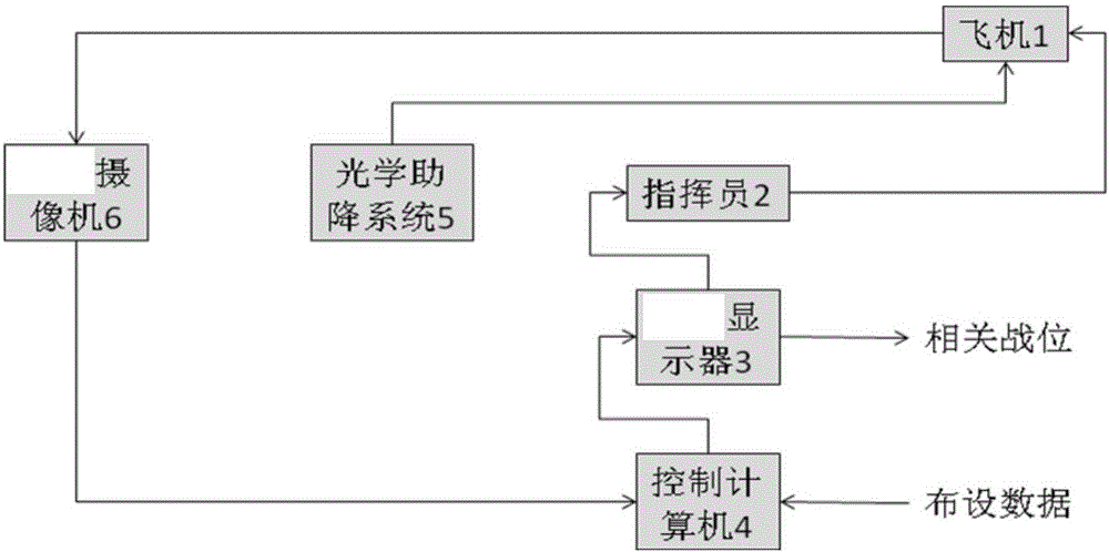
[0025] During installation, the camera 6 is installed on a pan / tilt that can adjust the horizontal and vertical angles, and the installation location is set according to the specific conditions of the airport. According to the relative relationship with the optical landing aid system 5, the spatial orientation angle of the camera 6...


PUM


Abstract

The invention relates to an aircraft landing surveillance guiding method. A camera is movably mounted on one side of the runway to guide the landing surveillance method. Step one: Determine the ideal landing point. Step two:Draw the ship stern line. Step three: Draw the finish line of the runway. Step four: Place the camera (6) on one side of the runway finish line. Step five:Connect the camera (6) to a control computer (4). The picture signal is sent by the control computer (4) to the monitor (3) to display in front of the commander (2). Step six: The commander (2) compares the aircraft deviation through the aircraft (1) image location and monitor (3) vertical and horizontal coordinate. Step seven: The commander (2) prompts the pilot to manipulate the aircraft (1). The commander (2) is capable of manipulating the aircraft (1) for landing training at any airfield that meets the basic training conditions.

Description

technical field [0001] The invention belongs to the field of aviation flight support, and in particular relates to a guiding method for monitoring and commanding the flight situation of the aircraft during the landing process of the aircraft. Background technique [0002] During the landing training of fixed-wing carrier-based aircraft, since the landing runway of the aircraft carrier is very short, the pilot must control the aircraft to slide down the ideal glideslope during the process of the aircraft sliding down the glideslope. If it cannot glide along the ideal glideslope, the aircraft will land. If the point is too close, too far, or deviates from the airstrip, a go-around, escape, or even a hard landing will occur; therefore, directing an aircraft to land on an aircraft carrier is a specialized knowledge that requires long-term training. In order to ensure that the fixed-wing carrier-based aircraft glides down the ideal glideslope, the precise command of the landing c...

Claims


Application Information

Patent Timeline
Patent Type & Authority Applications(China)
IPC IPC(8): B64F1/18
CPCB64F1/18
Inventor 吕善运王月基施恩国李敬通陈强田杰荣王文华崔焰张威叶兵王发龙
Owner NAVAL AVIATION UNIV
Why Eureka
Try Eureka