Optical structure, display panel and display device

An optical structure and display panel technology, applied in optics, identification devices, optical components, etc., can solve the problems of inability to realize image transformation, inability to realize video display, poor image authenticity, etc., and achieve the effect of holographic display

Inactive Publication Date: 2019-05-21
BOE TECH GRP CO LTD
View PDF1 Cites 0 Cited by
  • Summary
  • Abstract
  • Description
  • Claims
  • Application Information

AI Technical Summary

Problems solved by technology

[0004] At present, film is usually used as a dry plate, such as silver halide film with a resolution of 3000cy / mm, but this dry plate can only obtain static images, and cannot realize image transformation, that is, video display cannot be realized
Existing display devices, such as Liquid Crystal Display (Liquid Crystal Display, LCD), Organic Light-Emitting Diode (Organic Light-Emitting Diode, OLED), Micro Electro Mechanical System (Micro Electro Mechanical System, MEMS) display devices, etc., due to the image resolution of display devices The rate is far below the image resolution requirements of the holographic dry plate in the holographic display, so the authenticity of the displayed image is poor, and the holographic display of the object cannot be performed.

Method used


Image

  • Optical structure, display panel and display device
  • Optical structure, display panel and display device
  • Optical structure, display panel and display device

Examples


Embodiment Construction

[0038] In order to make the above objects, features and advantages of the present invention more comprehensible, the present invention will be further described in detail below in conjunction with the accompanying drawings and specific embodiments.

[0039] In the description of the present invention, unless otherwise stated, the meaning of "plurality" is two or more; the terms "upper", "lower", "left", "right", "inner", "outer" The orientation or positional relationship indicated by etc. is based on the orientation or positional relationship shown in the drawings, and is only for the convenience of describing the present invention and simplifying the description, rather than indicating or implying that the machine or element referred to must have a specific orientation, use a specific Azimuth configuration and operation, therefore, should not be construed as limiting the invention.

[0040] In the description of the present invention, it should be noted that unless otherwise ...


PUM


Abstract

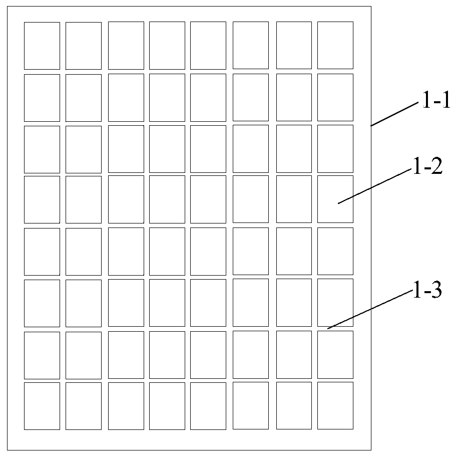
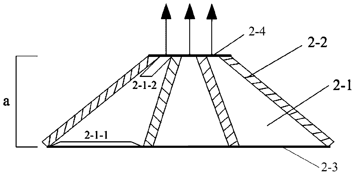
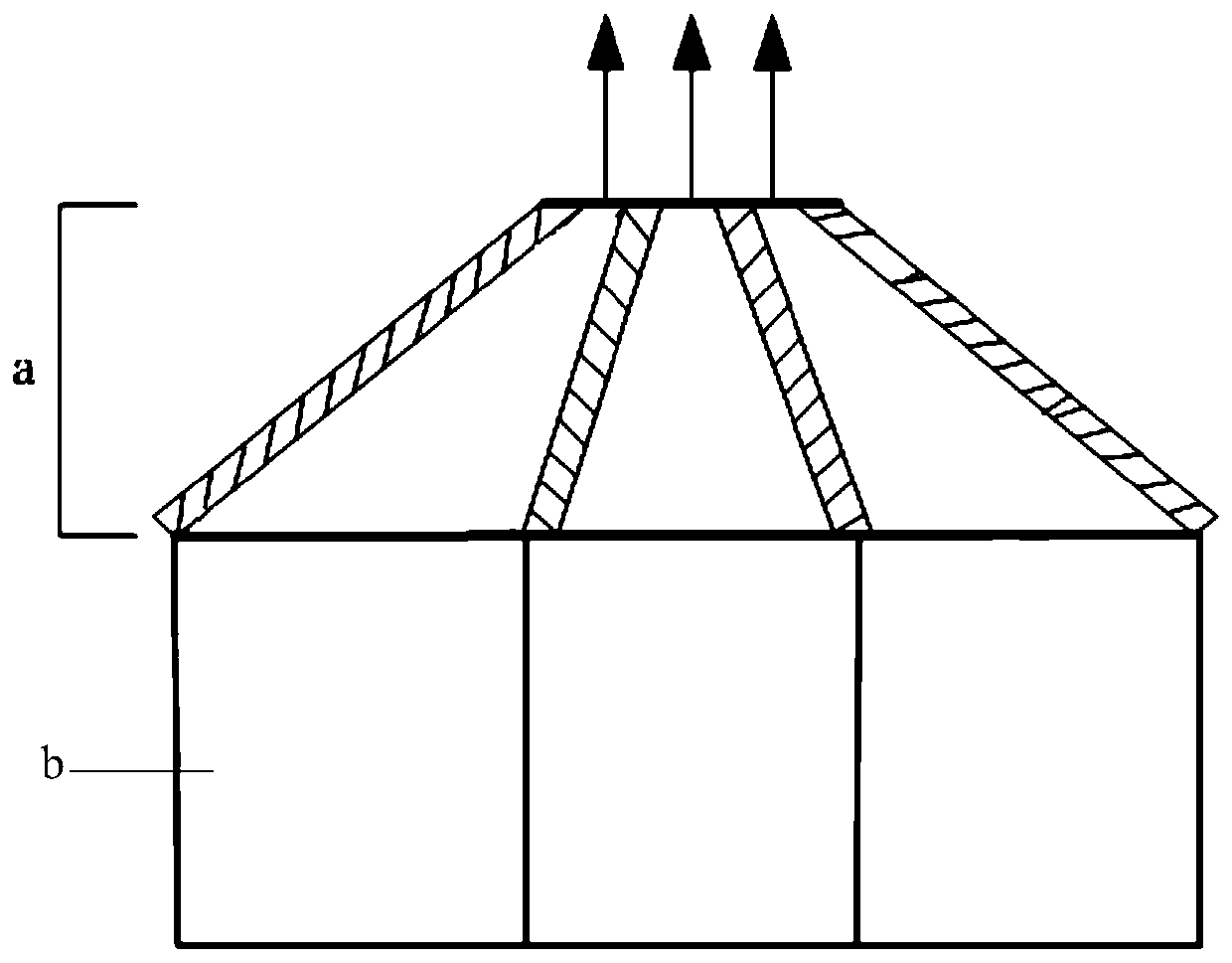
The invention provides an optical structure, a display panel and a display device. The optical structure is applied to the display panel; the optical structure comprises a base material; a plurality of independent optical chambers are formed in the base material; each optical chamber runs through the upper surface and the lower surface of the base material; the dimensions of light outlets, formed in the upper surface of the base material, of the optical chambers are less than those of light outlets, formed in the lower surfaces of the base material, of the optical chambers. The optical chambers have a reducing effect on the pixel of an image in the display panel, so that the pixel size of image displayed on the upper surface of the base material of the optical structure is reduced and the image resolution is enhanced; therefore, the images are clearly and truly displayed.

Description

technical field [0001] The invention relates to the field of display technology, in particular to an optical structure, a display panel and a display device. Background technique [0002] Holographic technology is a technology that uses the principles of interference and diffraction to record and reproduce the real three-dimensional images of objects. All physical and psychological cues. [0003] In the specific application of holographic technology, an interference image is formed on the holographic dry plate through the object light and reference light waves to record all the information of the object image, and the holographic image of the object is obtained by further using the reference light wave and the holographic dry plate image. Since the wavelength range of the visible light wave is 380-780nm, the wavelength of the interference fringes formed by the visible light wave within this range is within a considerable range, and the image resolution on the holographic dr...

Claims


Application Information

Patent Timeline
Patent Type & Authority Patents(China)
IPC IPC(8): G02F1/1335G09F9/33G02B26/08
CPCG02B26/0833G02F1/1335G02F1/133553G09F9/33
Inventor 关峰董学袁广才谷新王美丽王维谭纪风
Owner BOE TECH GRP CO LTD
Why Eureka
Try Eureka