High-safety electric power supply device

A technology of power supply and safety, which is applied in the direction of coupling devices, components of connecting devices, circuits, etc., can solve the problems of easy wear of plugs, poor contact of circuits, and low safety, so as to improve stability and accuracy, Improve the convenience of installation and reduce the effect of personnel operation

Active Publication Date: 2017-06-06
陕西德赛电气有限公司
View PDF5 Cites 14 Cited by
  • Summary
  • Abstract
  • Description
  • Claims
  • Application Information

AI Technical Summary

Problems solved by technology

[0002] The power supply device is one of the indispensable accessories of electric equipment, but the existing plug-in connectors have poor stability during use, troublesome operation, low safety, insufficient clamping force, and are easy to be dragged , Pulling and loosening, which will lead to poor contact of the circuit, affecting the normal use of electrical equipment, and after long-term use, the plug is prone to wear and tear, which will become looser and affect the service life. It is difficult to ensure the safety, reliability and stability of the electrical connection , and the operation is complicated, it is difficult to ensure fast plugging, which reduces work efficiency

Method used


Image

  • High-safety electric power supply device
  • High-safety electric power supply device
  • High-safety electric power supply device

Examples


Embodiment Construction

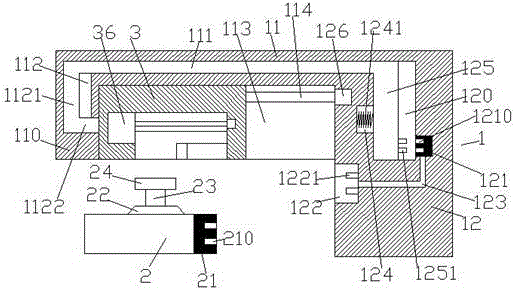
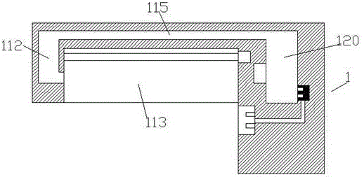
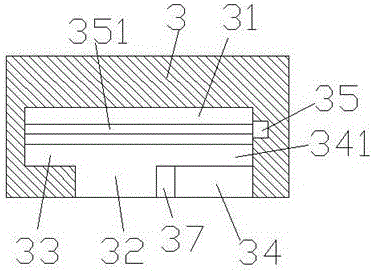
[0022] Such as Figure 1-Figure 6 As shown, a high-safety power supply device of the present invention includes a power supply base 1 composed of an execution part 11 and a power supply part 12, and a plug 2 for matching and connecting with the power supply base 1. A first chute 113 is provided at the lower right bottom of the execution part 11, and a first screw 114 is arranged inside the first chute 113, and the right end of the first screw 114 is power-connected with the first motor 126, and the first A screw rod 114 is provided with a locking guide slider 3 that is threadedly connected, and a second chute 31 is provided in the locking guide slider 3 , and a second screw rod 351 is provided in the second chute 31 . The right end of the two screw rods 351 is power-connected with the second motor 35, the bottom of the second chute 31 is provided with an installation groove 32, and the locking guide slider 3 on the left side of the installation groove 32 is provided with an ac...


PUM


Abstract

The invention discloses a high-safety electric power supply device, including a power supply base formed by an execution part and a power supply part and a plug piece used for being matched and connected with the power supply base, the bottom of the lower right side of the execution part is provided with a first sliding groove, a first screw is arranged in the first sliding groove, the right side end of the first screw is in power connection with a first motor, the first screw is provided with locking guide sliding blocks connected therewith in a screw-thread fit mode, a second sliding groove is arranged in the locking guide sliding block, a second screw is arranged in the second sliding groove, the right side end of the second screw is in power connection with a second motor, the bottom of the second sliding groove is provided with an installation groove, an accommodating cavity is arranged in the locking guide sliding block at the left side of the installation groove, a movable locking piece is arranged in the accommodating cavity, the top of the movable locking piece stretches into the second sliding groove and is in screw-thread fit with the second screw, a placing cavity is arranged in the locking guide sliding block at the right side of the installation groove, the lower side of the placing cavity is provided with a clamping groove, and an inclined plane guide sliding groove is arranged between the clamping groove and the installation groove.

Description

technical field [0001] The invention relates to the field of electric power technology, in particular to an electric power supply device with high safety. Background technique [0002] The power supply device is one of the indispensable accessories of electric equipment, but the existing plug-in connectors have poor stability during use, troublesome operation, low safety, insufficient clamping force, and are easy to be dragged , Pulling and loosening, which will lead to poor contact of the circuit, affecting the normal use of electrical equipment, and after a long period of use, the plug is prone to wear and tear, and then becomes looser, affecting the service life, making it difficult to ensure the safety, reliability and stability of the electrical connection , and the operation is complicated, it is difficult to ensure fast plugging, which reduces work efficiency. Contents of the invention [0003] The technical problem to be solved by the present invention is to provi...

Claims


Application Information

Patent Timeline
Patent Type & Authority Applications(China)
IPC IPC(8): H01R13/621H01R13/631H01R13/66
CPCH01R13/6215H01R13/631H01R13/665
Inventor 任薇薇
Owner 陕西德赛电气有限公司
Why Eureka
Try Eureka