Eureka AIR delivers breakthrough ideas for toughest innovation challenges, trusted by R&D personnel around the world.
Pipe String and Completion Methods
What is Al technical title?
Al technical title is built by PatSnap Al team. It summarizes the technical point description of the patent document.
A technology of tubing strings and tubing, applied in the field of oilfield development, can solve problems such as low work efficiency
Active Publication Date: 2019-02-15
PETROCHINA CO LTD
View PDF6 Cites 0 Cited by
Summary
Abstract
Description
Claims
Application Information
AI Technical Summary
This helps you quickly interpret patents by identifying the three key elements:
Problems solved by technology
Method used
Benefits of technology
Problems solved by technology
[0005] The invention provides a pipe string and a well completion method to overcome the work efficiency caused by the three functions of acid fracturing or acidizing transformation, self-flowing well completion and sand control in the prior art well completion operation, which requires three trips of drilling low defect
Method used
Image
Click on the blue label to locate the original text in one second.
Reading with bidirectional positioning of images and text.
Examples
Embodiment 1
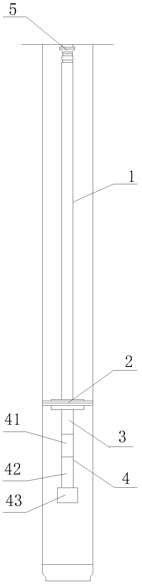
[0045] figure 1 It is a schematic structural diagram of a pipe string provided by an embodiment of the present invention. Refer to attached figure 1 As shown, this embodiment provides a pipe string, and the pipe string in this embodiment is mainly used in gushing wells.
[0046] The tubing string includes: a first tubing 1 , a packer 2 , a second tubing 3 , and a sand control device 4 arranged in sequence from top to bottom.
[0047] Specifically, the top end of the first oil pipe 1 is located at the wellhead, and the bottom end of the first oil pipe 1 communicates with the top end of the packer 2 . That is, the first oil pipe 1 is vertically arranged in the well. The bottom end of the packer 2 communicates with the top end of the second oil pipe 3 . It can be understood that: the packer 2 is a hollow structure, and the open end at the top of the hollow structure matches the bottom opening of the first oil pipe 1, so that the hollow structure communicates with the inside o...
Embodiment 2
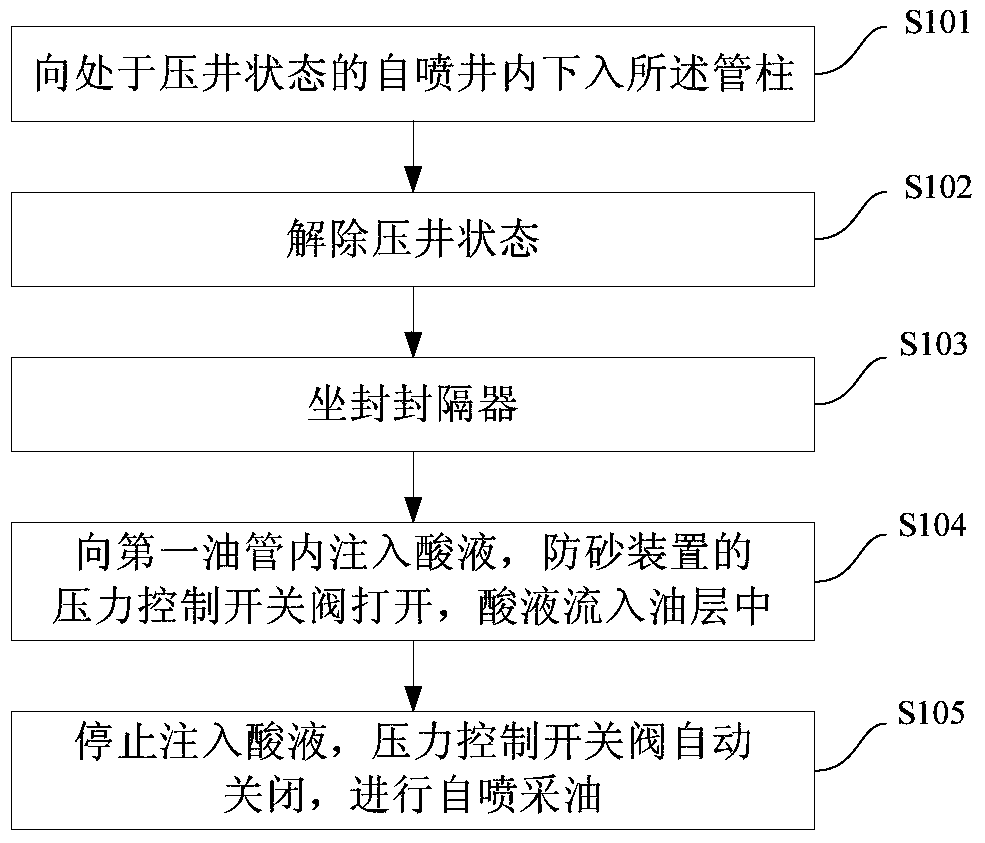
[0073] figure 2 It is a schematic flowchart of a well completion method provided by an embodiment of the present invention. Refer to attached figure 2 As shown, this embodiment provides a well completion method, which is realized by using the pipe string provided in Embodiment 1.
[0074] A well completion method comprising:
[0075] S101. Run the pipe string into the well-killing state of the flowing well.
[0076] Specifically, the killing state refers to injecting dense mud into the well to equal or slightly higher than the pore pressure of the formation, so as to suppress the energy of the formation so that it cannot self-spray.
[0077] Run the pipe string into the well so that the sand control device is located at the designed well depth, that is, the sand control device is located in the oil layer.
[0078] S102. Release the kill state.
[0079] Specifically, after the pipe string is run in, the annulus protection fluid with low density is injected into the annul...
PUM
Abstract
The invention provides a string and a well completion method; the string includes a first tube, a packer, a second tube, and a sand preventer arranged sequentially from top to bottom; the bottom end of the first tube is communicated with the top end of the packer; the bottom end of the packer is communicated with the top end of the second tube; the sand preventer includes a sand prevention tube, a sand settling tube and a pressure control switch valve connected sequentially from top to bottom; the top end of the sand prevention tube is communicated with the bottom end of the second tube, the bottom end of the sand prevention tube is communicated with the top end of the sand settling tube, and the side wall of the sand prevention tube is provided with a plurality of through holes admitting oi land gas; the pressure control switch valve is arranged at the bottom of the sand settling tube and may be opened or closed under the action of fluid pressure in the tubing. The functions of acid fracturing or acidifying modification, flowing well completion and sand prevention can be achieved just through the trip-in of the string, operating time is shortened, and working efficiency is improved.
Description
technical field [0001] The invention relates to the technical field of oilfield development, in particular to a pipe string and a well completion method. Background technique [0002] In the process of oil field development, well completion operations are required. Among them, well completion operations are not only the last process of drilling operations, but also the beginning of oil production operations. Well completion operations play an important role in connecting drilling operations and oil production operations. In the process of well completion, acid fracturing or acidizing technology is usually required to increase the permeability of the formation, so as to achieve the purpose of self-flowing oil and gas wells and increase oil and gas production. In oil recovery operations, the formation of the self-flowing well has the energy to lift oil and gas from the oil and gas layer to the wellhead. In addition, many formations also produce sand while producing oil, so the...
Claims
Application Information
Patent Timeline
Application Date:The date an application was filed.
Publication Date:The date a patent or application was officially published.
First Publication Date:The earliest publication date of a patent with the same application number.
Issue Date:Publication date of the patent grant document.
PCT Entry Date:The Entry date of PCT National Phase.
Estimated Expiry Date:The statutory expiry date of a patent right according to the Patent Law, and it is the longest term of protection that the patent right can achieve without the termination of the patent right due to other reasons(Term extension factor has been taken into account ).
Invalid Date:Actual expiry date is based on effective date or publication date of legal transaction data of invalid patent.