A process and device for preventing water hammer in LNG pipelines
A process method and water hammer technology, applied in the pipeline system, mechanical equipment, gas/liquid distribution and storage, etc., can solve the problems of inapplicability, and achieve the effects of easy processing, reasonable design and convenient use
- Summary
- Abstract
- Description
- Claims
- Application Information
AI Technical Summary
Problems solved by technology
Method used
Image
Examples
Embodiment 1
[0020] Configuration device:
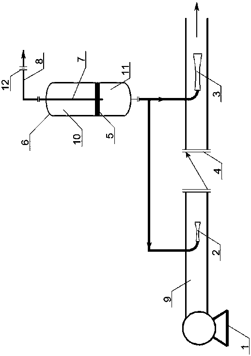
[0021] The device for preventing water hammer in LNG pipelines includes an LNG pump 1 and a buffer tank 6, a check valve 4 is installed in the middle of the outlet pipeline 9 of the LNG pump 1, and the outlet pipeline 9 on the upstream side of the check valve 4 is Injector 1 2 is arranged inside, and injector 2 3 is arranged in the outlet pipeline 9 of the downstream part on the other side of check valve 4; the nozzle direction of injector 1 2 and injector 2 3 is in line with the normal liquid outlet direction of LNG pump 1 same.
[0022] The outlet pipes at the bottom of the buffer tank 6 communicate with the first injector 2 and the second injector 3 respectively, and the top of the buffer tank 6 communicates with the cold preservation circulation pipeline 8 on which a flow-restricting orifice 12 is arranged. The inside of the buffer tank 6 is radially equipped with a separation plate 5, and the inner cavity of the buffer tank 6 at the top of ...
Embodiment 2
[0025] Configuration device:
[0026] The device for preventing water hammer in LNG pipelines includes an LNG pump 1 and a buffer tank 6, a check valve 4 is installed in the middle of the outlet pipeline 9 of the LNG pump 1, and the outlet pipeline 9 on the upstream side of the check valve 4 is Injector 1 2 is arranged inside, and injector 2 3 is arranged in the outlet pipeline 9 of the downstream part on the other side of check valve 4; the nozzle direction of injector 1 2 and injector 2 3 is in line with the normal liquid outlet direction of LNG pump 1 same.
[0027] The outlet pipes at the bottom of the buffer tank 6 communicate with the first injector 2 and the second injector 3 respectively, and the top of the buffer tank 6 communicates with the cold preservation circulation pipeline 8 on which a flow-restricting orifice 12 is arranged. The inside of the buffer tank 6 is radially equipped with a separation plate 5, and the inner cavity of the buffer tank 6 at the top of ...
Embodiment 3
[0030] Configuration device:
[0031] The device for preventing water hammer in the LNG pipeline includes an LNG pump 1 and a buffer tank 6, a check valve 4 is installed in the middle of the outlet pipeline 9 of the LNG pump 1, and the outlet pipeline 9 on the upstream side of the check valve 4 is Injector 1 2 is arranged inside, and injector 2 3 is arranged in the outlet pipeline 9 of the downstream part on the other side of check valve 4; the nozzle direction of injector 1 2 and injector 2 3 is in line with the normal liquid outlet direction of LNG pump 1 same.
[0032] The outlet pipes at the bottom of the buffer tank 6 communicate with the first injector 2 and the second injector 3 respectively, and the top of the buffer tank 6 communicates with the cold preservation circulation pipeline 8 on which a flow-restricting orifice 12 is arranged. The inside of the buffer tank 6 is radially equipped with an isolation plate 5, and the inner cavity of the buffer tank 6 at the top ...
PUM
 Abstract
Description
Claims
Application Information
 - R&D
- Intellectual Property
- Life Sciences
- Materials
- Tech Scout
- Unparalleled Data Quality
- Higher Quality Content
- 60% Fewer Hallucinations
Browse by: Latest US Patents, China's latest patents, Technical Efficacy Thesaurus, Application Domain, Technology Topic, Popular Technical Reports.
© 2025 PatSnap. All rights reserved.Legal|Privacy policy|Modern Slavery Act Transparency Statement|Sitemap|About US| Contact US: help@patsnap.com

