Integrated self-condensation drainage device

A self-condensing, integrated technology, applied in steam traps, mechanical equipment, etc., can solve problems such as water hammer and achieve the effect of reducing water hammer

Pending Publication Date: 2021-04-13
BEIJING PETROCHEM ENG
View PDF0 Cites 0 Cited by
  • Summary
  • Abstract
  • Description
  • Claims
  • Application Information

AI Technical Summary

Problems solved by technology

All steam traps have back pressure. For example, the condensate produced by 0.6Mpa steam passing through the trap must be lower than 0.6Mpa. The conventional design of chemical plants is that 0.6Mpa steam drains into the 0.3Mpa condensate pipe, but because the condensate enters the 0.3Mpa After the condensate tube of Mpa, the pressure drop will inevitably flash, and the steam of 0.3Mpa will flash out in the condensate tube, causing the condensate tube to become a steam tube again, and at the same time, it contains a large amount of condensate, which will inevitably cause water hammer Phenomenon

Method used


Image

  • Integrated self-condensation drainage device
  • Integrated self-condensation drainage device
  • Integrated self-condensation drainage device

Examples


Embodiment Construction

[0044] In order to have a clearer understanding of the technical solutions, objectives and effects of the present invention, the specific implementation manners of the present invention will now be described with reference to the accompanying drawings.

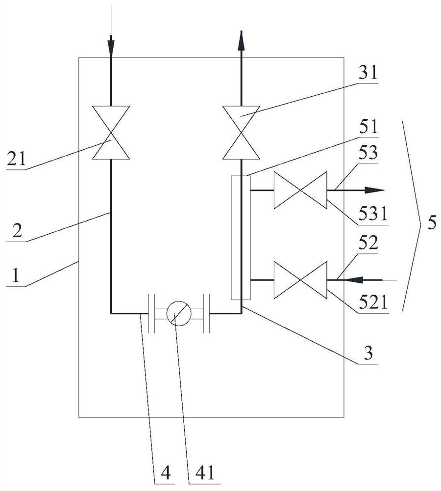
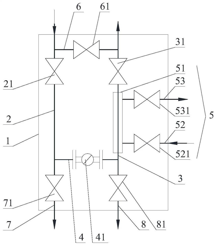
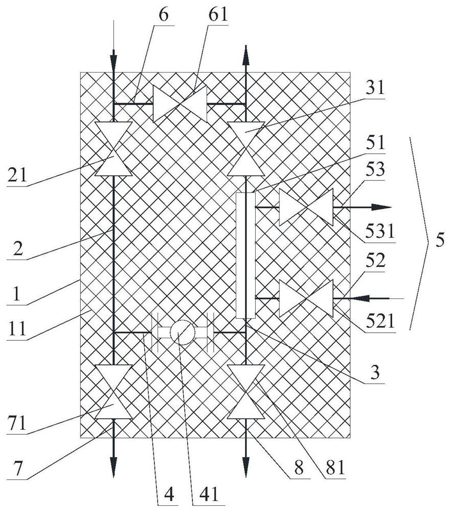
[0045] Such as Figure 1 ~ Figure 3 As shown, the present invention provides an integrated self-condensing drainage device, wherein the integrated self-condensing drainage device includes a housing 1, a steam pipeline 2, a condensate pipeline 3 and a drainage pipeline 4, a steam pipeline 2, a condensate pipeline 3 and The drain pipelines 4 are all arranged inside the shell 1, the first end of the steam line 2 runs through the shell 1 and communicates with the outside of the shell 1, the second end of the steam line 2 communicates with the first end of the drain line 4, and the second end of the steam line 4 communicates with the outside of the shell 1. The two ends communicate with the first end of the condensate pipeline 3, t...


PUM


Abstract

The invention provides an integrated self-condensation drainage device. The device comprises a shell, a steam pipeline, a condensate pipeline and a drainage pipeline, wherein the steam pipeline, the condensate pipeline and the drainage pipeline are all arranged in the shell, the first end of the steam pipeline is in communication with the exterior of the shell, the second end of the steam pipeline is in communication with the first end of the drainage pipeline, the second end of the drainage pipeline is in communication with the first end of the condensate pipeline, the second end of the condensate pipeline is in communication with the exterior of the shell, a drainage valve is arranged on the drainage pipeline, and a cooling assembly is arranged on the condensate pipeline. The device is installed at the low point or the tail end wherein a condensate is generated of an existing steam pipe, the steam pipeline is in communication with the existing steam pipe, the condensate pipeline is in communication with an existing condensate pipe, the condensate generated in the existing steam pipe enters the steam pipeline and flows through the condensate pipeline through the drainage valve of the drainage pipeline to be drained into the existing condensate pipe, when the condensate is flash-evaporated into steam through the drainage valve to enter the condensate pipeline, the condensate is condensed again into condensate through the cooling assembly, and thus the steam generated through flash evaporation can be effectively treated, and the water hammer phenomenon is reduced.

Description

technical field [0001] The invention relates to a condensation hydrophobic structure in the chemical production process, in particular to an integrated self-condensing hydrophobic device. Background technique [0002] In chemical plants, there are multiple steam specifications, such as: 9.8Mpa, 4.1Mpa, 2.5Mpa, 1.4Mpa, 0.6Mpa, etc. Each specification of steam may produce condensate, and the condensed water in the steam pipeline will cause the steam to be heated. Even, the latent heat of steam will be lost, and it may cause corrosion to equipment and pipelines, and may even cause water hammer, icing, vibration and other phenomena in the steam pipeline. Steam traps can remove non-condensable gases such as steam condensate and air in steam heating equipment or steam pipelines without leaking steam. It is mainly installed in places where condensation may occur in steam pipes, including low points of steam, steam heating or heat tracing ends, etc. All steam traps have back press...

Claims


Application Information

Patent Timeline
Patent Type & Authority Applications(China)
IPC IPC(8): F16T1/00F16T1/38
CPCF16T1/00F16T1/38
Inventor 张雷
Owner BEIJING PETROCHEM ENG
Why Eureka
Try Eureka