
A motor automatic winding machine

An automatic winding machine and winding technology, which is applied in the direction of electric components, manufacturing motor generators, electromechanical devices, etc., can solve the problem of inability to effectively realize automatic and efficient winding of motor coils, poor coil uniformity, reliability and stability, and affect the motor Quality and energy consumption and other issues, to achieve the effect of improving coil winding efficiency, ensuring winding tightness, and increasing wire feeding speed

Inactive Publication Date: 2019-04-26
山西海康圣达煤机有限公司
View PDF4 Cites 0 Cited by
  • Summary
  • Abstract
  • Description
  • Claims
  • Application Information

AI Technical Summary

Problems solved by technology

There are many types of motors, but there are stators and rotors inside, and conductive coils are wound on the stators or rotors. Using the principle of electromagnetic induction, the stators or rotors with conductive coils rotate under the action of a magnetic field, so the winding of the coils is It is a necessary link in the production of motors. If manual winding is used, it will be time-consuming, laborious and inefficient. Moreover, the uniformity and reliability of the manually wound coils are poor, which seriously affects the quality and energy consumption of the motor. The existing motor Due to the backwardness of the structure, the coil winding machine also has the disadvantages of low efficiency and poor stability, and cannot effectively realize the automatic and efficient winding of the motor coil

Method used


Image

  • A motor automatic winding machine
  • A motor automatic winding machine
  • A motor automatic winding machine

Examples


Embodiment Construction

[0034] In order to enable those skilled in the art to better understand the technical solution of the present invention, the present invention will be described in detail below in conjunction with the accompanying drawings. The description in this part is only exemplary and explanatory, and should not have any limiting effect on the protection scope of the present invention. .

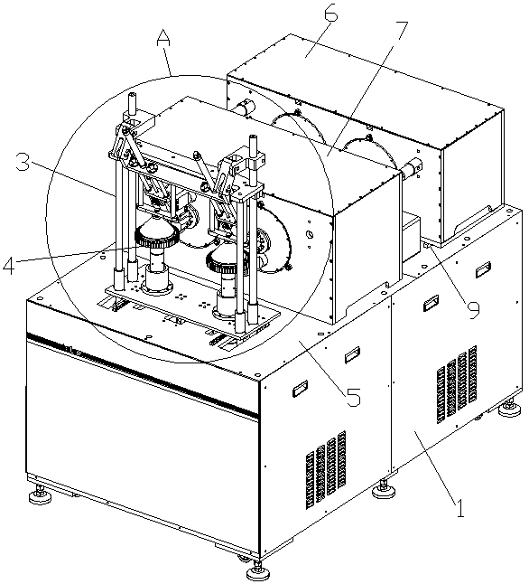
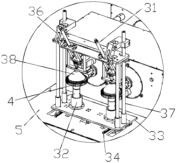
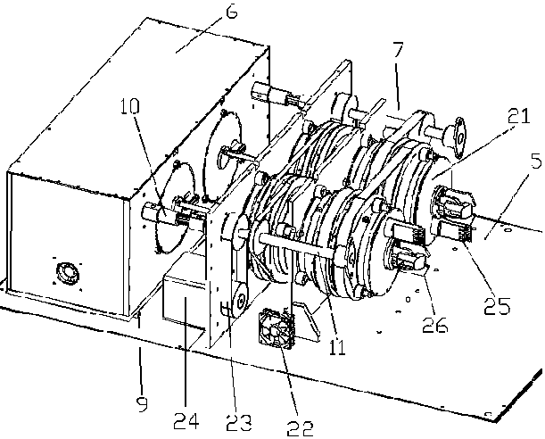
[0035] like Figure 1-Figure 13 As shown, the structural connection relationship of the present invention is: an automatic motor winding machine, which includes a power distribution control box 1, the upper end of the power distribution control box 1 is provided with a table panel 5; The rear wire feeding box 6 and the front wire feeding box 7; the front end of the front wire feeding box 7 is provided with a winding device 3; the rear wire feeding box 6 and the table panel 5 are provided with a wire feeding box guide rail 9; The bottom surface of the rear wire feeding box 6 is connected with the wire ...


PUM


Abstract

The invention discloses a wire feeding mechanism for motor winding. The wire feeding mechanism comprises a power distribution control cabinet, a rear wire feeding box, a front wire feeding box and a winding device, wherein the rear wire feeding box is connected with a wire feeding motor; wire coils are arranged in the rear wire feeding box and the front wire feeding box; the wire coils are connected with wire coil motors; wire feeding tubes are arranged at inner side edges of the wire coils; winding guide heads and wire feeding heads are arranged at the front end of the wire coils; in the winding device, a winding bottom plate is connected with a clamping motor; a rotating shaft connected with a rotating motor is arranged on the winding bottom plate; sliding rods are arranged on two sidesof the winding bottom plate; the lower ends of the sliding rods are connected with push air cylinders and the upper ends of the sliding rods are connected with hinge plates; winding guide clamps are arranged on the hinge plates; and a conical pressure head which is located on a U-shaped plate is arranged above the rotating shaft. The wire feeding mechanism is capable of realizing the full-automatic winding of product coils, is stable and reliable in coil winding, good in uniformity and high in winding speed, and is capable of greatly improving the motor production efficiency and reducing the labor intensity of workers.

Description

technical field [0001] The invention relates to the technical field of motor coil winding, in particular to an automatic motor winding machine. Background technique [0002] Electric motors, commonly known as motors, are the power source of various electrical appliances and mechanical equipment. It can realize the conversion of electric energy and kinetic energy. There are many types of motors, but there are stators and rotors inside, and conductive coils are wound on the stators or rotors. Using the principle of electromagnetic induction, the stators or rotors with conductive coils rotate under the action of a magnetic field, so the winding of the coils is It is a necessary link in the production of motors. If manual winding is used, it will be time-consuming, laborious and inefficient. Moreover, the uniformity, reliability and stability of the manually wound coils are poor, which seriously affects the quality and energy consumption of the motor. The existing motor Due to...

Claims


Application Information

Patent Timeline
Patent Type & Authority Patents(China)
IPC IPC(8): H02K15/04
CPCH02K15/0435
Inventor 不公告发明人
Owner 山西海康圣达煤机有限公司
Learn More