
A Gain Control Method of Vector Modulator

A vector modulator and gain control technology, applied in the digital field, can solve the problems of a lot of test data and time-consuming, and achieve the effect of improving gain flatness, reducing errors, improving performance and calibration efficiency

Active Publication Date: 2020-08-18
BEIJING AEROSPACE MEASUREMENT & CONTROL TECH
View PDF4 Cites 0 Cited by
  • Summary
  • Abstract
  • Description
  • Claims
  • Application Information

AI Technical Summary

Problems solved by technology

[0005] In order to obtain high-precision gain flatness and phase offset, in practical applications, it is necessary to test a vector modulator under different environments such as frequency, temperature and power. The test data is extremely large and takes a lot of time

Method used


Image

  • A Gain Control Method of Vector Modulator
  • A Gain Control Method of Vector Modulator
  • A Gain Control Method of Vector Modulator

Examples


Embodiment Construction

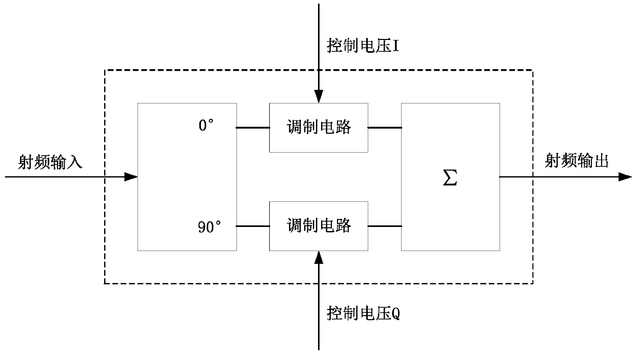
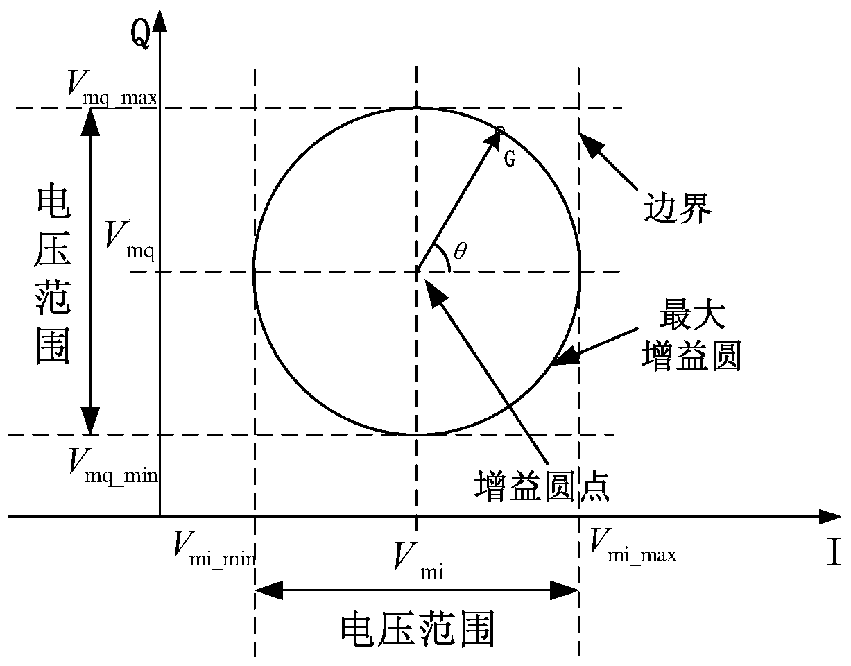
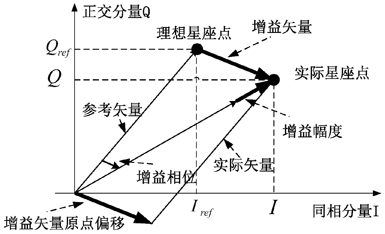
[0042] The invention provides a gain control method of a vector modulator. By realizing the automatic test based on the maximum gain circle, the gain control of the vector modulator can be accurately realized, the errors caused by the phase offset and the amplitude offset can be minimized, and the obtained The maximum gain value of the modulator improves the gain flatness, thereby correcting the synthesized vector signal and improving the performance and calibration efficiency of the vector modulator. The present invention will be described in further detail below in conjunction with the accompanying drawings and embodiments. It should be understood that the specific embodiments described here are only used to explain the present invention, not to limit the present invention.

[0043] An embodiment of the present invention provides a method for controlling the gain of a vector modulator, the method including a coarse calibration test and a fine calibration test;

[0044] The ...


PUM


Abstract

The invention discloses a gain control method of a vector modulator. The method comprises coarse alignment testing and fine alignment testing, wherein the coarse alignment testing comprises the steps of setting an I-path alignment boundary and a Q-path alignment boundary for coarse alignment testing; selecting coarse alignment stepping for I-path and Q-path; testing gain control of the vector modulator according to the I-path alignment boundary and coarse alignment stepping and the Q-path alignment boundary and coarse alignment stepping in the testing; and verifying whether the control voltage corresponding to the I-path minimum gain value and the control voltage corresponding to the Q-path minimum gain value, which are obtained in the testing, can meet preset amplitude flatness and phase offset index or not, and if so, outputting the control voltages corresponding to I-path and Q-path minimum gain values obtained in the testing, otherwise performing fine alignment testing. The method can be used for effectively improving the performance and alignment efficiency of a vector modulator.

Description

technical field [0001] The invention relates to the field of digital technology, in particular to a gain control method of a vector modulator. Background technique [0002] At present, the quadrature modulator has been widely used in the fields of radar, navigation, instrumentation, and satellite communication. It has the characteristics of small structure, low power consumption, and low modulation loss. Amplitude, so as to realize the phase shift and amplitude change of the signal. [0003] A quadrature vector modulator has a pair of control circuits. Two control signals I and Q form a two-dimensional plane. At the same frequency point, combining different control voltages can produce different combinations of gain and phase data, which can be used to define The magnitude of the RF signal gain and the phase of the gain. For a vector modulator that can work normally, if the precision of the control voltage is small enough and the voltage is within the normal operating rang...

Claims


Application Information

Patent Timeline
Patent Type & Authority Patents(China)
IPC IPC(8): H03C3/09H03G3/30
CPCH03C3/0991H03G3/30
Inventor 吕佳胡韵泽张秋艳
Owner BEIJING AEROSPACE MEASUREMENT & CONTROL TECH
Learn More