
Feeding trough capable of controlling discharge

A technology for feed troughs and buckets, which is applied in the field of feed troughs, can solve the problems of wasting feed and inconvenient use.

Inactive Publication Date: 2017-06-13
安徽菲扬新材料有限公司
View PDF4 Cites 3 Cited by
  • Summary
  • Abstract
  • Description
  • Claims
  • Application Information

AI Technical Summary

Problems solved by technology

[0003] The announcement number is CN204722007U, and the announcement date is October 28, 2015. A Chinese utility model patent discloses a feeding trough for pigs, including a food bin and a feeding trough. , the food bin is fixed on the fixed frame, the lower part of the food bin is provided with a feeding tube, and a regulating tube is set inside the feeding tube, the position of the regulating tube in the feeding tube can be adjusted up and down, and the position of the lower nozzle of the regulating tube and the bottom of the trough can be changed. The distance, the adjustment tube is positioned by the fixing screw and the feeding pipe, and there are fixed plates on both sides of the feeding trough; the feeding trough is a stainless steel disc with a thickness of 2~3mm. The feeding trough controls the feeding of feed to prevent pigs from wasting feed. Save feeding costs, but due to a single design problem, problems such as feed blockage and uneven distribution of feed cannot be avoided, resulting in inconvenient use

Method used


Image

  • Feeding trough capable of controlling discharge
  • Feeding trough capable of controlling discharge
  • Feeding trough capable of controlling discharge

Examples


Embodiment Construction

[0019] Below in conjunction with specific embodiment, further illustrate the present invention. These examples are only for illustrating the present invention and are not intended to limit the scope of the present invention.

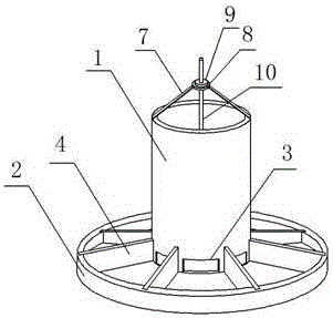
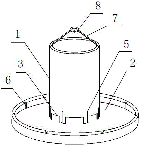
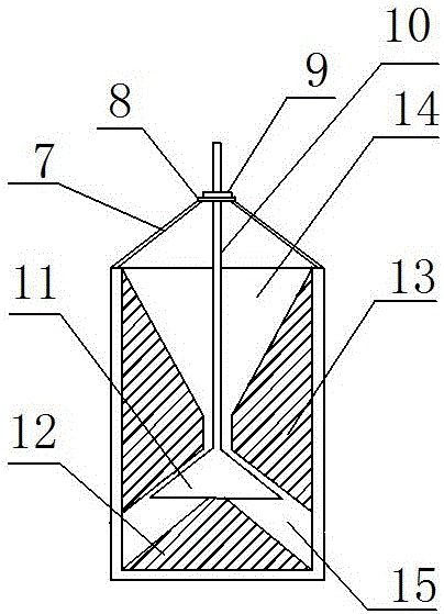
[0020] Such as Figure 1~4 In the shown embodiment of the present invention, a feed trough with controllable discharge is provided, which includes a lower feed tank 1 with an open top, a tank body 2 positioned at the bottom of the lower feed tank 1, the tank body 2 is disc-shaped, and the lower feed tank 1. The side wall is provided with a discharge port 3. The feed trough of this embodiment has the functions of uniform distribution of materials, controllable discharge and prevention of clogging.

[0021] A tray 8 is arranged above the feeding barrel 1, and at least two connecting rods 7 are arranged on the top of the feeding barrel 1. The other ends of the connecting rods 7 are connected to the side wall of the tray 8. The tray 8 is a ring structure, a...


PUM


Abstract

The invention discloses a feeding trough capable of controlling discharge, and relates to the technical field of pig breeding equipment. The feeding trough comprises a discharge tank with a top opening and a trough body located at the bottom of the discharge tank. The trough body is disc-shaped, and a partition is installed inside the trough body. A discharge port is arranged on the side wall of the discharge tank, and a tray is arranged above the discharge tank. At least two connecting rods are installed at the top of the discharge tank, and the other ends of the connecting rods are connected with the side wall of the tray. The tray is of a ring structure, and a rotating shaft is vertically arranged in the center of the tray. The rotating shaft is provided with a reinforcing piece, and the reinforcing piece is located above the tray. A flow guiding block is installed on the inner wall of the discharge tank, and a feed distribution block is installed at the bottom of the discharge tank. The discharge tank is divided by the flow guiding block and the feed distribution block into a first cavity and a second cavity which are arranged up and down, wherein the first cavity is a funnel-shaped structure and the first cavity is communicated with the second cavity. The rotating shaft passes through the first cavity and the second cavity, and the bottom of the rotating shaft is provided with a guide vane which is located inside the second cavity. The feeding trough capable of controlling discharge has the functions of uniform feed distribution, controllable discharge and blocking prevention.

Description

technical field [0001] The invention relates to the technical field of pig raising equipment, in particular to a feed trough with controllable output. Background technique [0002] China has a long history of raising livestock, and there are written records of raising pigs as early as the Xia and Shang dynasties. More than a thousand years ago, Chinese working people began to raise livestock, and then gradually formed a scale. Livestock production has the characteristics of high reproductive rate, strong adaptability, and easy management. It has been widely raised in the vast agricultural and pastoral areas of China. Breeding in captivity allows livestock to develop in a balanced manner, and can also make rational use of feed. The utilization rate of feed is relatively high, and it is easy to form a breeding scale and increase the commodity rate. [0003] The announcement number is CN204722007U, and the announcement date is October 28, 2015. A Chinese utility model patent ...

Claims


Application Information

Patent Timeline
Patent Type & Authority Applications(China)
IPC IPC(8): A01K5/01
CPCA01K5/01
Inventor 岳朝雷
Owner 安徽菲扬新材料有限公司
Learn More