Bi-directional gear transmission artificial hand

A two-way gear and prosthetic hand technology, applied in prosthesis, medical science, artificial arm and other directions, can solve the problems of low stability, heavy weight and weak function of the bionic hand, and achieve compact and simplified structure, high transmission efficiency, weight reduction effect

Active Publication Date: 2017-06-13
BEIJING INSTITUTE OF TECHNOLOGYGY
View PDF7 Cites 9 Cited by
  • Summary
  • Abstract
  • Description
  • Claims
  • Application Information

AI Technical Summary

Problems solved by technology

[0004] In order to solve the problems of the above-mentioned existing passive prosthetic hands that are not strong enough to meet the daily needs of disabled patients, and the mec

Method used


Image

  • Bi-directional gear transmission artificial hand
  • Bi-directional gear transmission artificial hand
  • Bi-directional gear transmission artificial hand

Examples


Embodiment 1

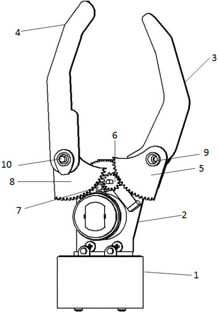
[0025] see figure 1 and figure 2 As shown, the present invention provides a two-way gear transmission prosthetic hand, including a body, the body includes a fixed part and a movable part, the fixed part includes a connecting end 1 for wearing and a palm end 2 for installing driving parts, and the movable part includes two groups The first group of artificial fingers 4 and the second group of artificial fingers 3 arranged symmetrically; the palm end 2 is vertically arranged above the connection end 1 through several connection nuts, and different connection ends can be selected according to the user's wearing position (such as matching wrist or elbow), more user-friendly. The bottom of the artificial finger is fixed on the palm end 2 through the rotating shaft 9, 10, and the artificial finger can rotate around the rotating shaft as the center of a circle, and the first arc-shaped gear 8 and the second arc-shaped gear 8 are fixedly connected to the rotating shaft 9, 10 respect...

Embodiment 2

[0028] Such as Figure 6 and Figure 7 As shown, the difference between Embodiment 2 and Embodiment 1 is that: the first group of artificial fingers 4 includes two artificial fingers arranged in parallel, and the two artificial fingers are fixedly connected through the connecting shaft 15 so that the two artificial fingers can perform synchronous rotational movement , the rotation planes of the two artificial fingers of the first group of artificial fingers 4 and the second group of artificial fingers 3 are staggered from each other.

Embodiment 3

[0030] The difference between Embodiment 3 and Embodiment 1 is that: the palm end 2 is provided with a total of four limit devices at the movement limit position corresponding to the meshing state of the arc gear and the gear shaft.


PUM


Abstract

The invention discloses a bi-directional gear transmission artificial hand. The bi-directional gear transmission artificial hand comprises a fixed part and a mobile part, the fixed part comprises a connection end and a palm end, the mobile part comprises symmetrically arranged two groups of artificial fingers, and arc gears are arranged below the artificial fingers; a drive element comprises a drive motor and a main gear, the gear center of the main gear extends in the horizontal direction to form a gear shaft, the gear shaft is meshed with a first arc gear, and a reversing gear is arranged between the gear shaft and a second arc gear. In the bi-directional gear transmission artificial hand, gear transmission is adopted, due to stability of the gear transmission, the artificial hand has a stable and fixed transmission ratio, the grasping speed of the artificial hand is controlled more easily, and accordingly the grasping motion is completed naturally; besides, by utilizing the bi-directional transmission characteristic of multiple meshed gears, the movement of the two groups of artificial fingers are controlled through one motor, thus the whole artificial hand is more compact and simplified in structure, the weight of the artificial hand is lowered, the production cost is controlled, and the comfort that handicapped personnel wear the artificial hand is improved at the same time.

Description

technical field [0001] The invention relates to a medical rehabilitation device for persons with upper limb disabilities, in particular to a two-way gear transmission prosthetic hand. Background technique [0002] Upper limb prosthesis is an artificial prosthesis specially designed and manufactured to make up for the defects of upper limb amputee or incompletely missing limbs by means and methods of engineering technology. Its main function is to replace part of the functions of the lost limb and restore the limb A certain degree of self-care and work ability. Upper limb prostheses are currently mainly divided into decorative upper limb prostheses, tool hands, traction mechanical prostheses, electric prostheses, and myoelectric prostheses. With the development of science and technology, artificial limbs are developing towards the trend of intelligence, light weight and active control. In order for the prosthetic hand to be promoted to the commercial market, a stable and re...

Claims


Application Information

Patent Timeline
IPC IPC(8): A61F2/54A61F2/70
CPCA61F2/583A61F2/586A61F2/68A61F2002/6836
Inventor 佘浩田孙文涛朱金营李鑫张笑华黄强
Owner BEIJING INSTITUTE OF TECHNOLOGYGY
Why Eureka
Try Eureka