Suspension type ultrasonic atomization generator and humidifier

A technology of ultrasonic atomization and generator, applied in the direction of air humidification system, heating method, lighting and heating equipment, etc., can solve the problems of unmaintainable, difficult maintenance, harsh use conditions, etc., achieve simple structure, convenient use, and get rid of dependence Effect

Inactive Publication Date: 2017-06-13
缪其明
View PDF8 Cites 6 Cited by
  • Summary
  • Abstract
  • Description
  • Claims
  • Application Information

AI Technical Summary

Problems solved by technology

[0004] 2. Where the epoxy resin flows, it solidifies with the electronic components of the ultrasonic atomization generator, making maintenance difficult or even impossible, resulting in losses;
[0005] 3. In order to make the ultrasonic atomization generator continue to work normally, it is necessary to add a set of automatic liquid supply and liquid level detection devices, and to supply liquid continuously, which is inconvenient to use and not conducive to promotion
[0008] 2. In order to make the ultrasonic atomization generator continue to work normally, a set of automatic liquid supply and liquid level detection device must be installed, and the continuous liquid supply makes the structure of the humidifier more complicated and the conditions of use are harsh;

Method used


Image

  • Suspension type ultrasonic atomization generator and humidifier
  • Suspension type ultrasonic atomization generator and humidifier
  • Suspension type ultrasonic atomization generator and humidifier

Examples


Embodiment 1

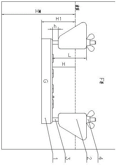
[0048] Example 1, see figure 1 , install connectors at both ends of the body of the ultrasonic atomization generator, the connectors are round rods with threads at one end, one end of the connectors is fixedly connected with the body of the ultrasonic atomizer, and then the floating bodies are respectively set on the connectors Then install the wing nuts on the connecting piece respectively, the wing nut adjusts the position of the floating body on the connecting piece, the distance from the highest point of the floating body to the working surface of the ultrasonic atomizing generator is greater than the normal working distance of the ultrasonic atomizing generator The depth of the liquid level, the total buoyancy is greater than the total gravity, the bottom of the floating body is small, and the top is large, which is conducive to the balance and stability of the suspended ultrasonic atomization generator; the wing nut may be replaced by an ordinary nut.

Embodiment 2

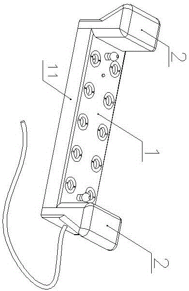
[0049] Example 2, see figure 2 , on the shell of the ultrasonic atomizing generator body, two floating bodies are symmetrically arranged left and right. The floating bodies are pasted on the left and right sides of the outer surface of the shell of the ultrasonic atomizing generator body. The distance is greater than the liquid level depth of the normal working of the ultrasonic atomization generator, and the total buoyancy generated by the two floating bodies is greater than the total gravity of the suspension type ultrasonic atomization generator. The balance and stability of the generator.

Embodiment 3

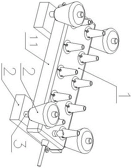
[0050] Example 3, see image 3 , at the bottom of the body of the ultrasonic atomization generator, two floating bodies are symmetrically fixedly installed, and connecting pieces are respectively fixed symmetrically on both sides of the two floating bodies. The connecting piece is a cylindrical rod, and the other end of the cylindrical rod is provided with a screw thread , in addition, on the four cylindrical rods, internally threaded floating bodies are respectively installed. The floating body is a cone with the small end facing down and the large end facing upwards. The floating body can rotate up and down along the thread provided on the cylindrical rod. , the distance from the highest point of the floating body to the working surface of the ultrasonic atomization generator is greater than the liquid level depth of the normal operation of the ultrasonic atomization generator, and the total buoyancy generated by all the floating bodies is greater than the total gravity of th...


PUM


Abstract

The invention discloses a suspension type ultrasonic atomization generator and a humidifier. The suspension type ultrasonic atomization generator comprises an ultrasonic atomization generator body (1), and is characterized by further comprising a floating body (2), wherein the total buoyancy of the floating body (2) is larger than the total gravity of the suspension type ultrasonic atomization generator. The humidifier comprises the suspension type ultrasonic atomization generator (100), a cabinet body (200) and a fan (300), wherein the cabinet body is closed; an outlet (201) is formed in one end at the upper part of the cabinet body, and an inlet (202) is formed in the other end of the upper part of the cabinet body; the fan is arranged at the inlet; and the suspension type ultrasonic atomization generator is placed in the cabinet body. The defects of the ultrasonic atomization generator in the prior art and the humidifier using the ultrasonic atomization generator in the prior art are overcome.

Description

technical field [0001] The invention relates to the field of ultrasonic atomization generators and humidifiers, in particular to a suspended ultrasonic atomization generator and humidifier. Background technique [0002] Ultrasonic atomization generators in the prior art use an epoxy resin layer as a sealing medium, which is a commonly used solution. They are all installed on the bottom of the container during use, which has the following obvious disadvantages: [0003] 1. The density of the ultrasonic atomization generator is very high. In order to facilitate sinking to the bottom of the container, its density is much higher than that of the atomized liquid, so it is heavy; [0004] 2. Where the epoxy resin flows, it solidifies with the electronic components of the ultrasonic atomization generator, making maintenance difficult or even impossible, resulting in losses; [0005] 3. In order to make the ultrasonic atomization generator continue to work normally, it is necessary...

Claims


Application Information

Patent Timeline
Patent Type & Authority Applications(China)
IPC IPC(8): B05B17/06F24F6/12F24F13/00F24F11/02
CPCF24F6/12F24F11/89F24F13/00B05B17/06Y02B30/70B05B17/0615
Inventor 缪其明
Owner 缪其明
Why Eureka
Try Eureka