Gear automatic reaming device

A gear and reaming technology, which is applied in reaming devices, reaming devices, metal processing, etc., can solve the problems of not being able to effectively guarantee the accuracy of gear reaming, reduce the efficiency of gear processing, and increase the labor intensity of producers. Effects of improving production efficiency and production accuracy, improving efficiency, and improving convenience

Pending Publication Date: 2019-09-06
浙江鑫和粉末冶金制品有限公司
View PDF0 Cites 1 Cited by
  • Summary
  • Abstract
  • Description
  • Claims
  • Application Information

AI Technical Summary

Problems solved by technology

[0002] In the production process of gears, the center hole generally needs to be reamed or reamed. However, the method of reaming gears with a conventional drilling machine is generally to manually place the gear workpiece in the fixture by the producer, and then ream the gears in turn through the drilling machine. Processing, this method of manually reaming the gears by the producer, that is, every time a gear is processed, the gear needs to be disassembled and reamed. The entire operation process is manually discharged by the producer, which is extremely inefficient. The manual tightening of the fixture not only increases the labor intensity of the producer and reduces the efficiency of the producer's processing of the gear, but also easily causes problems such as reaming deviation or reaming slip due to the installation omission of the gear installed on the fixture , the reaming accuracy of the gear cannot be effectively guaranteed, which affects the production quality of the gear

Method used


Image

  • Gear automatic reaming device
  • Gear automatic reaming device
  • Gear automatic reaming device

Examples


Embodiment Construction

[0022] The preferred embodiments of the present invention will be described in detail below with reference to the accompanying drawings, so that the advantages and features of the present invention can be more easily understood by those skilled in the art, and the protection scope of the present invention can be more clearly defined.

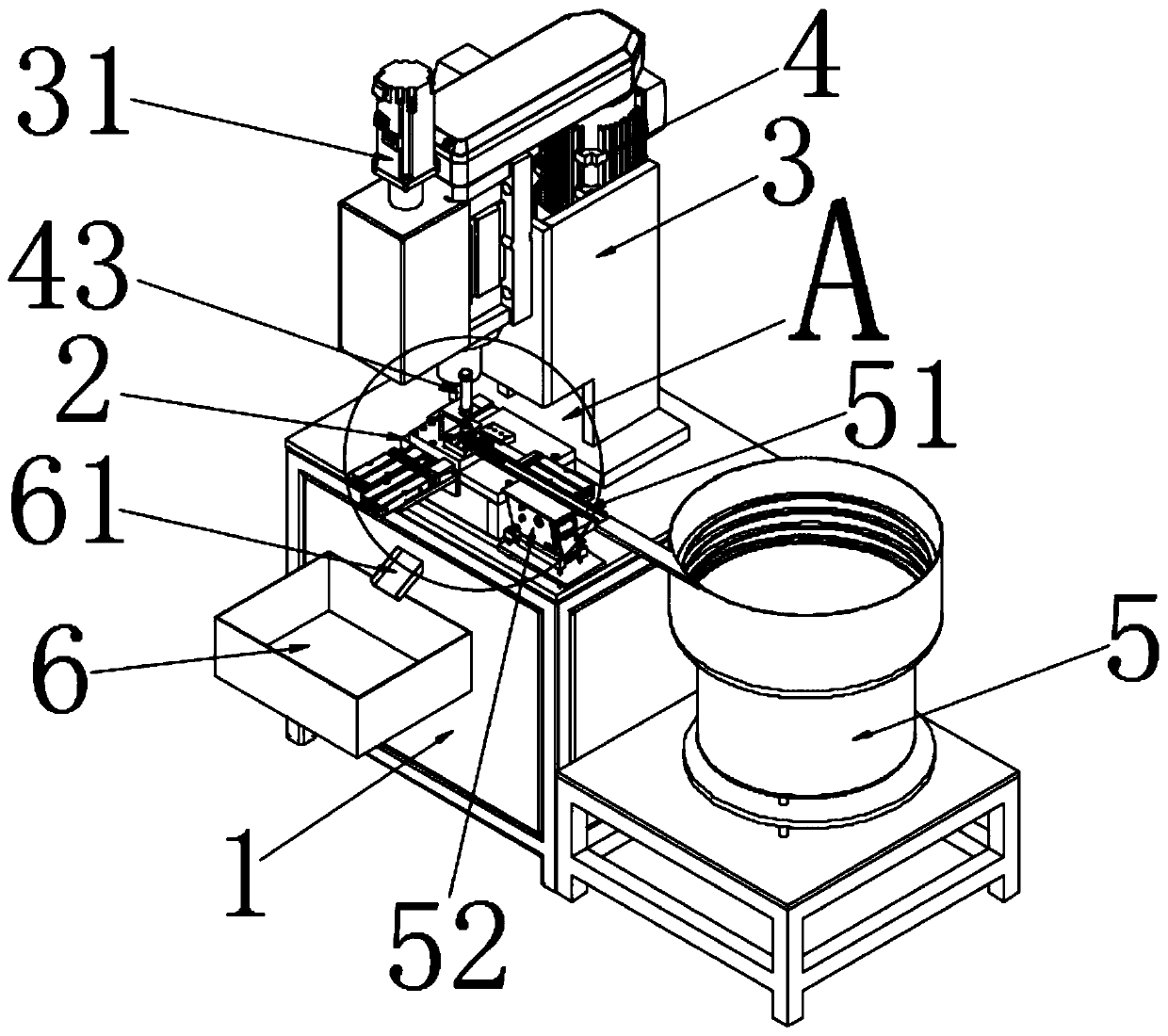
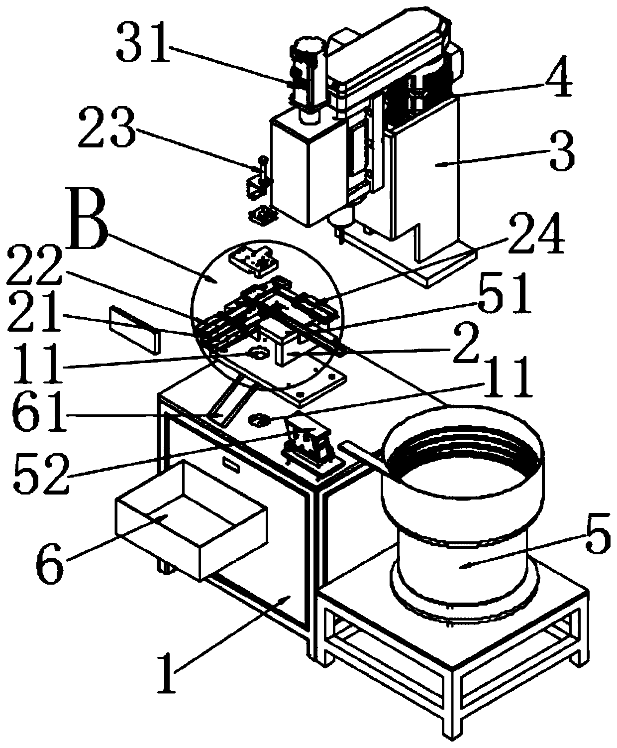
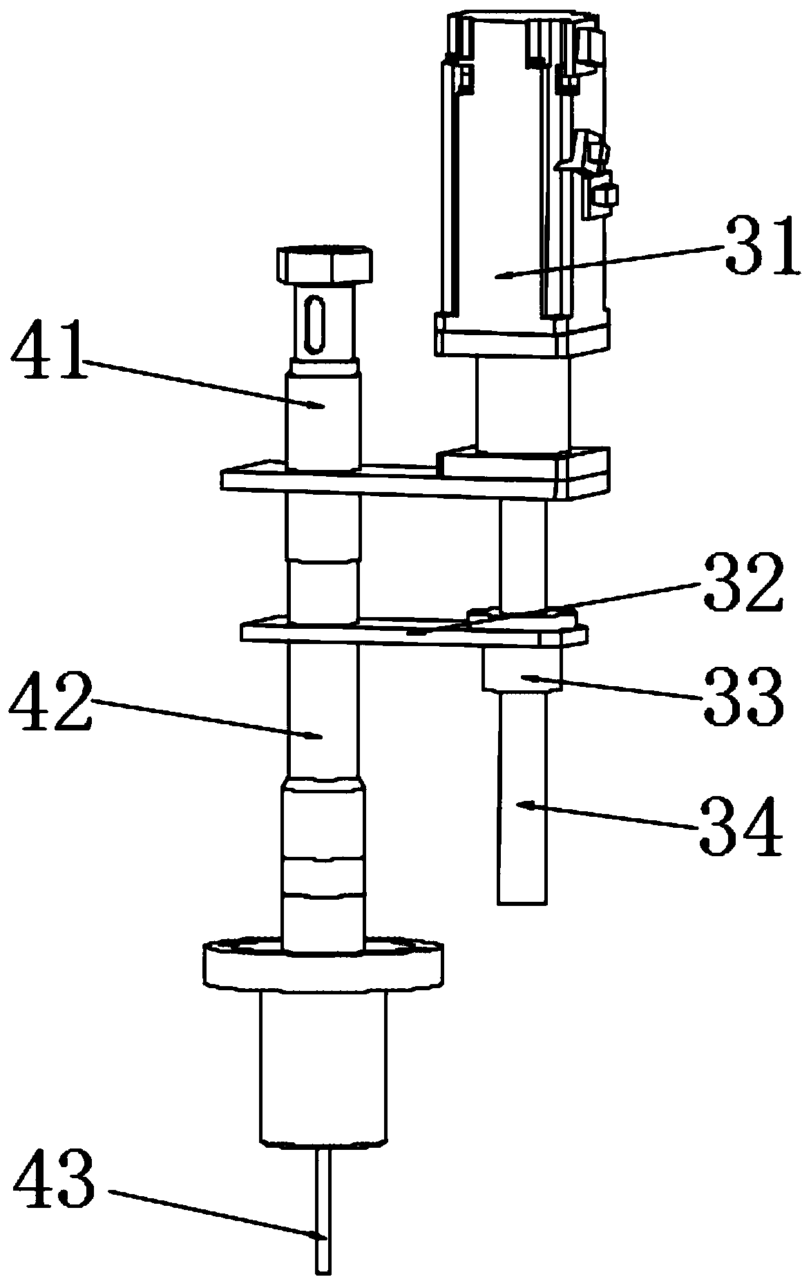
[0023] like Figure 1 to Figure 5 The shown gear automatic reaming device includes a workbench 2, a drive mechanism (not marked) connected above the workbench 2 for gear reaming, and a pre-storage device connected above the workbench 2 for storing gears. Block 231, a feed cylinder 24 is connected to the side of the worktable 2, a slideway 25 is provided on the surface of the workbench 2, and a feeder plate 221 slidably arranged in the slideway 25 is connected to the piston rod of the cylinder feeder 22. , the center of the slideway 25 is provided with a drop hole 251 that penetrates through the workbench 2 , the upper part of the drop hole 251 i...


PUM


Abstract

The invention discloses a gear automatic reaming device. The device comprises a workbench and a driving mechanism connected to the workbench and used for carrying out gear reaming, pre-storage blocksused for storing a gear is connected on the workbench, a slide way is arranged on the surface of the workbench, a falling hole penetrating through the workbench is formed in the center of the slide way, a slidable movable conveying plate is arranged inside the slide way, abutting blocks used for limiting movement of the gear is connected to the exact upper portion of the falling hole, the two sides of the pre-storage block are provided with a pushing cylinder used for pushing the gear inside the pre-storage block and a clamping block used for limiting displacement of the gear respectively, a moving cylinder used for pushing the gear is connected to the side of the clamping block, and a moving plate which is in the same straight line as a lock groove is connected to a piston rod of the moving cylinder. The gear automatic reaming device can automatically carry out reaming machining on the gear, the precision and the quality of gear production and machining are effectively improved, and the production efficiency and the production convenience of gear machining by producers are improved.

Description

technical field [0001] The invention relates to a gear automatic reaming device. Background technique [0002] In the production process of gears, the center hole generally needs to be reamed or reamed, while the conventional drilling machine reams the gears by manually placing the gear workpiece in the fixture, and then reaming the gears in turn by the drilling machine. Processing, this method of reaming the gears manually by the manufacturer, that is, the gear disassembly and reaming are required for each processing of the gears. The manual tightening of the fixture not only increases the labor intensity of the producer, but also reduces the efficiency of the producer's processing of the gear. It is also easy to cause problems such as reaming deviation or reaming slip due to the installation of the gear on the fixture. , the reaming accuracy of the gear cannot be effectively guaranteed, and the quality of the gear production is affected. SUMMARY OF THE INVENTION [000...

Claims


Application Information

Patent Timeline
Patent Type & Authority Applications(China)
IPC IPC(8): B23D75/00B23Q7/00
CPCB23D75/00B23Q7/00
Inventor 杨清陈承志张天震徐小斌左小丰
Owner 浙江鑫和粉末冶金制品有限公司
Why Eureka
Try Eureka