
sliding reamer

A technology of reaming and spiral bands, which is applied in the field of design and manufacture of reamers used in oil fields, can solve the problems of drill sticking, single usage, inflexibility and convenience, etc., and achieve the effect of improving service life

Active Publication Date: 2016-09-21
YANGZHOU CHICHENG GASOLINEEUM MACHINERY
View PDF6 Cites 0 Cited by
  • Summary
  • Abstract
  • Description
  • Claims
  • Application Information

AI Technical Summary

Problems solved by technology

[0002] The sliding reamer is designed to drill holes during the sliding operation. At present, the common reamer used in the market has a small torque during the reaming process. The pulling force on the device is relatively large and it is easy to cause the drill to be stuck, and the function of the ordinary reamer can only meet the requirements of reaming, and the usage is single, not flexible and convenient

Method used


Image

  • sliding reamer
  • sliding reamer
  • sliding reamer

Examples


Embodiment 1

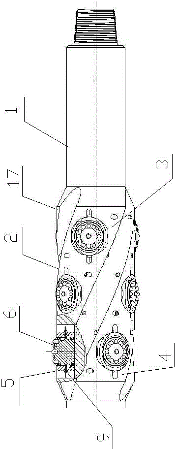
[0026] Such as figure 1 , 3 Shown, the present invention comprises drill string body 1, is provided with reaming section 2 on drill string body 1, and reaming section 2 is the cylinder structure that diameter increases; Band 3, the second spiral band 4, the third spiral band 17; the starting point of the first spiral band 3 and the stop point of the second spiral band 4 are on the same plane passing the axis; in the first spiral band 3, the second The working surfaces of the spiral belt 4 and the third spiral belt 17 are respectively provided with wheel body installation grooves 5; in each wheel body installation groove 5, a cone assembly 6 is respectively detachably arranged.

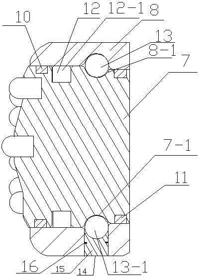
[0027] Each cone assembly 6 includes a cone 7 and a fixed sleeve 8; the fixed sleeve 8 is connected to the wheel body installation groove 5 through a threaded pin 9; a first "U"-shaped seal is provided between the cone 7 and the fixed sleeve 8 Ring 10, second "U"-shaped sealing ring 11, roller group ...

Embodiment 2

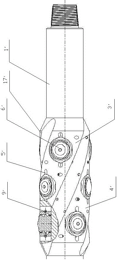
[0033] Such as figure 2 , 4 Shown, the present invention comprises drill string body 1 ', is provided with reaming section 2 ' on drill string main body 1 ', and described reaming section 2 ' is the cylinder structure that diameter increases; The first helical band 3', the second helical band 4', and the third helical band 17' are arranged on the outer peripheral surface; On the plane; wheel body installation grooves 5' are respectively set on the working surfaces of the first spiral belt 3', the second spiral belt 4' and the third spiral belt 17'; each wheel body installation groove 5' is detachable Set up the centralizing wheel assembly 6'.

[0034] Each righting wheel assembly 6' includes a righting wheel 7' and a fixed sleeve 8' respectively; the fixed sleeve 8' is connected to the wheel body installation groove 5' through a threaded pin 9'; Set the first "U"-shaped sealing ring 10', the second "U"-shaped sealing ring 11', the roller set 12', the steel ball set 13'; fr...


PUM


Abstract

The invention discloses a sliding hole winging machine, and relates to the technical field of design and manufacture of a hole winging machine used in an oil field. The sliding hole winging machine comprises a drill column body, and a hole swinging section is arranged on the drill column body; the peripheral face of the hole swinging section is provided with a first spiral band, a second spiral band and a third spiral band; wheel body installation grooves are formed in working faces of the first spiral band, the second spiral band and the third spiral band respectively; tooth wheel components are arranged in the wheel body installation grooves in a detachable mode respectively. A cylinder body of the sliding hole winging machine can be changed rapidly, by replacing with hard tooth wheels, the sliding hole winging machine can serve as a sliding centralizer used for centralizing a drill column and underground drilling tool components, meanwhile the sliding hole winging machine can rotate uniquely, drilling is prevented from being clamped, the hole swinging efficiency is improved, the use is convenient, and the flexibility and multiple purposes are achieved.

Description

technical field [0001] The invention relates to the technical field of design and manufacture of reamers used in oil fields. Background technique [0002] The sliding reamer is designed to drill holes during the sliding operation. At present, the common reamer used in the market has a small torque during the reaming process. The pulling force on the reamer is relatively large and it is easy to cause drill sticking, and the function of ordinary reamers can only satisfy reaming, and the usage is single, not flexible and convenient. Contents of the invention [0003] The object of the present invention is to provide a sliding reamer which can avoid drill sticking, improve reaming efficiency, and is convenient, flexible and multi-purpose. [0004] The present invention includes a drill string body, on which a reaming section is arranged, and the reaming section is a cylindrical structure with an enlarged diameter; on the outer peripheral surface of the reaming section, a firs...

Claims


Application Information

Patent Timeline
Patent Type & Authority Patents(China)
IPC IPC(8): E21B17/10E21B10/08
CPCE21B10/08E21B10/25E21B10/26E21B17/10E21B17/1078
Inventor 金学宏葛志磊
Owner YANGZHOU CHICHENG GASOLINEEUM MACHINERY
Learn More