

Glass coating wiping equipment
A glass and equipment technology, applied in the field of glass coating production equipment, can solve the problems of unstable overall operation, poor overall versatility, discounted use effect, etc., and achieve the effect of realizing automatic operation, ensuring the cleanliness of wiping, and reasonable structure
- Summary
- Abstract
- Description
- Claims
- Application Information
AI Technical Summary
Problems solved by technology
Method used
Image

Examples
Embodiment Construction
[0034] The following will clearly and completely describe the technical solutions in the embodiments of the present invention with reference to the drawings in the embodiments of the present invention.
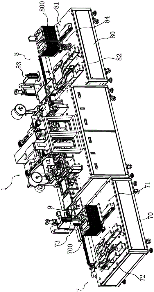
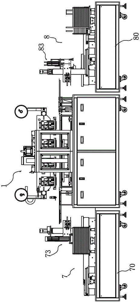
[0035] Figure 1~2As shown, the glass coating wiping equipment includes a feeding device 7, a retrieving device 8 and a wiping device 1 between them. The wiped glass piece 9 is placed in the feeding tray 700, and then the stacked feeding tray 700 is placed on the feeding device 7, and the glass piece 9 is transported to the wiping device 1 by the feeding device 7 for wiping operation. After the wiping is completed, the wiped glass parts 9 are placed in the retrieving tray 800 of the retrieving device 8, stacked neatly and then taken out. The whole process is completed by the equipment itself without manual operation.
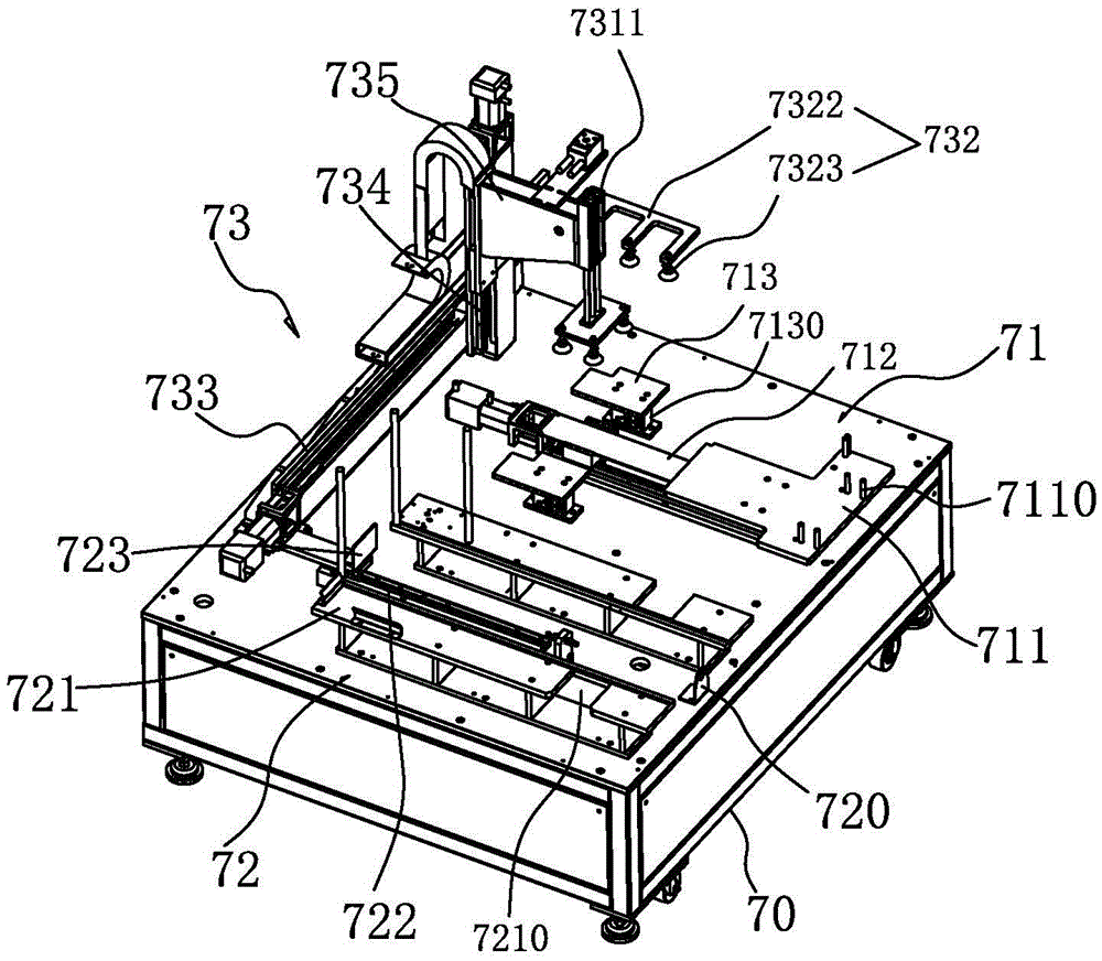
[0036] combine image 3 , 4 , 5 and 6, the feed device 7 includes: a feed base 70, and a feed tray feeding mechanism 71 arranged on the feed base 70, a feed...
PUM
 Abstract
Description
Claims
Application Information