Sheet metal stamping device

A stamping device and plate technology, applied in the direction of stamping machines, electromechanical devices, presses, etc., can solve the problems of low safety factor, personal injury, etc., and achieve the effects of improving safety, convenient control, and simple operation

Active Publication Date: 2018-07-06
DOOR IND CO LTD CHONGQING DTOMO
View PDF1 Cites 2 Cited by
  • Summary
  • Abstract
  • Description
  • Claims
  • Application Information

AI Technical Summary

Problems solved by technology

However, in actual work, when the hand of the unloading operator has not exited the punching range of the punch, if the punching operator turns on the switch by mistake at this time, the punching head will punch to the hand of the unloading operator, causing personal injury. Low

Method used


Image

  • Sheet metal stamping device
  • Sheet metal stamping device
  • Sheet metal stamping device

Examples


Embodiment Construction

[0023] The present invention will be described in further detail below by means of specific embodiments:

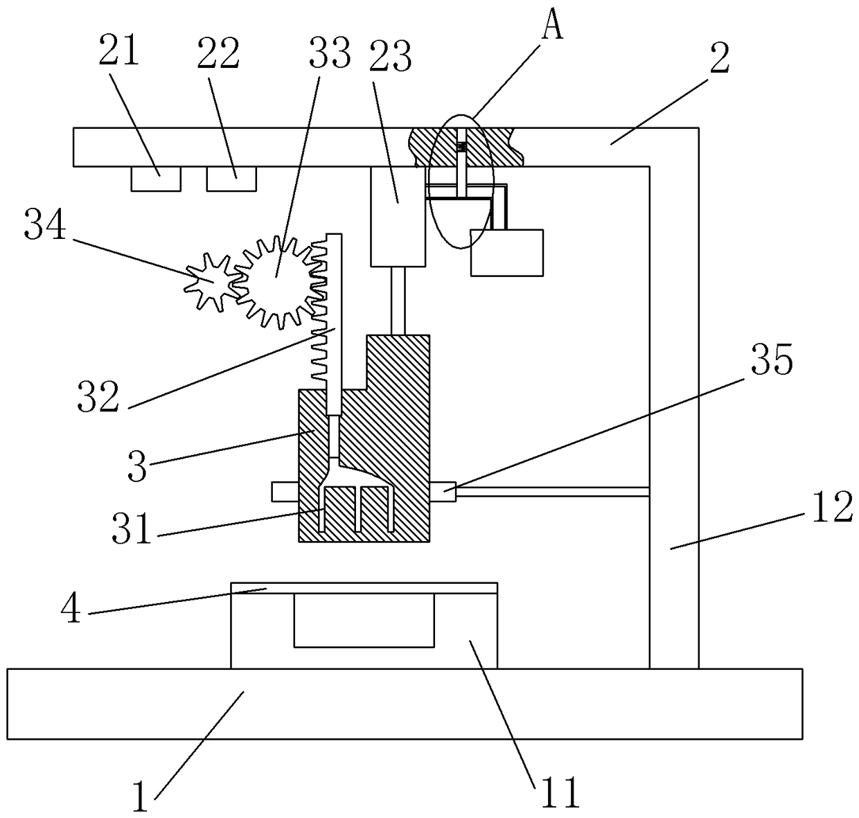
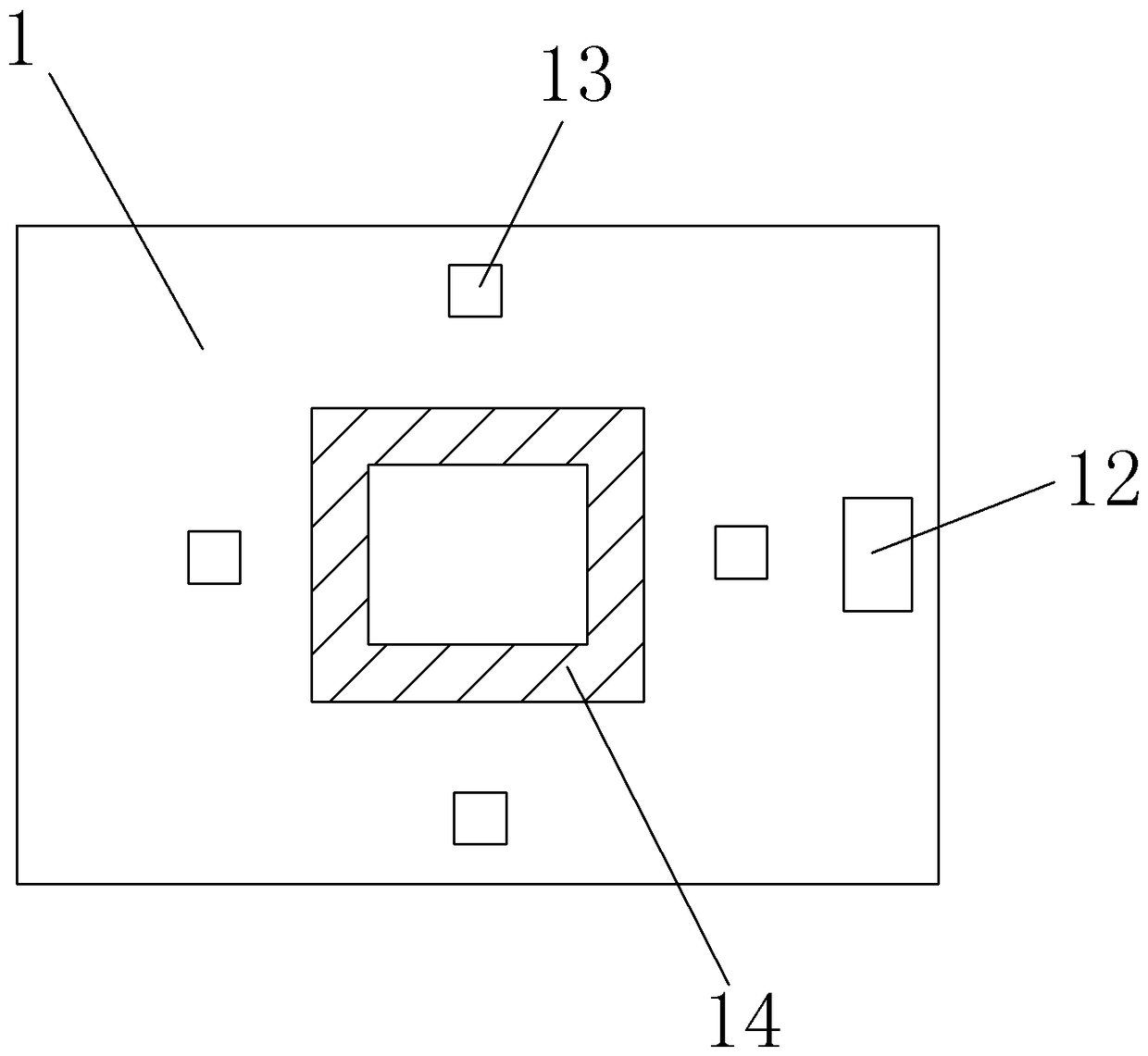
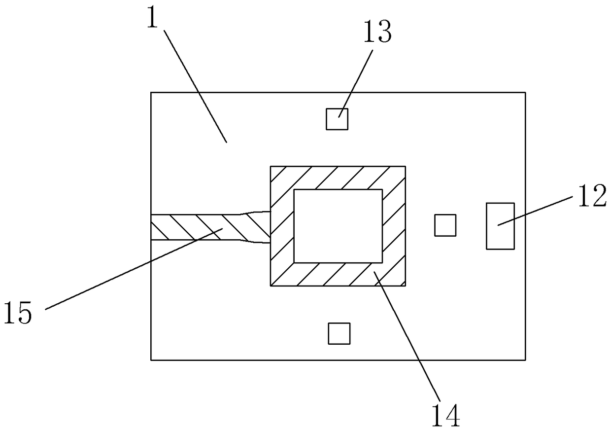
[0024] The reference signs in the accompanying drawings include: base 1, mounting base 11, bracket 12, photoelectric switch 13, safety shadow area 14, hand shadow area 15, mounting frame 2, first storage battery 21, second storage battery 22, cylinder 23 , intake pipe 24, spool 25, electromagnetic block 26, stamping head 3, air collecting tank 31, first rack 32, first gear 33, second gear 34, light source 35, generator 36, plate 4.

[0025] The embodiment is basically as attached figure 1 Shown: the sheet metal stamping device, including a base 1, a mounting seat 11 is arranged on the upper part of the base 1, and a mounting groove is opened on the mounting seat 11, and a stamping die is placed in the mounting groove, and a number of photoelectric devices are distributed on the upper part of the base 1 There are 4 switches 13 and photoelectric switches 13 in total. The 4...


PUM


Abstract

Disclosed is a sheet stamping device. The sheet stamping device comprises a base and a mounting base. A stamping die is arranged in the mounting base. A support is arranged on one side of the base, and a mounting frame is connected to the support. An air cylinder is arranged at the bottom of the mounting frame, a stamping head is connected to the air cylinder, an air inlet pipe is connected to an air inlet of the air cylinder, and a valve element is connected to the air inlet pipe in a sliding mode. A mounting hole is formed in the mounting frame, and the valve element stretches into the mounting hole. An electromagnet is further arranged in the mounting hole, and an excitation coil is arranged on the electromagnet. A plurality of air collecting grooves are formed in the stamping head. A piston is arranged in a piston cavity, and a piston tail portion stretches out of the stamping head and is connected with a first rack. An electric generator is connected to a rotating shaft. Photoelectric switches are further arranged on the base. The sheet stamping device further comprises two storage batteries and a light source. By the adoption of the scheme, the hidden danger that before the hands of a worker leave from a stamping region, due to the misoperation, the air cylinder drives the stamping head to move downwards, and the safety is the worker is affected is avoided.

Description

technical field [0001] The invention relates to a plate processing device. Background technique [0002] Stamping forming refers to the process of applying external force to plates, strips, pipes and profiles by presses and molds to cause plastic deformation or separation, so as to obtain workpieces (stamping parts) of required shape and size. In the prior art, plates are mostly processed by stamping. [0003] For example, in Chinese Patent No. ZL201521065076.9, a quick-release plate stamping device is disclosed, including a base, one side of the base is provided with a fixed plate, and a compression cylinder is installed on the fixed plate through an arc-shaped plate, and the piston of the compression cylinder The end is connected with a pressing plate, the pressing plate passes through the guide plate set on the fixed plate, the lower end of the pressing plate is provided with a stamping plate, and the base below the stamping plate is provided with an installation groove ...

Claims


Application Information

Patent Timeline
Patent Type & Authority Patents(China)
IPC IPC(8): B21D55/00B21D22/02B30B1/38H02K7/18
CPCB21D22/02B21D55/00B30B1/38H02K7/1815
Inventor 万贤平
Owner DOOR IND CO LTD CHONGQING DTOMO
Why Eureka
Try Eureka