Industrial equipment punching machine

A technology of industrial equipment and drilling machine, which is applied in the direction of metal processing equipment, drilling/drilling equipment, manufacturing tools, etc., can solve the problems of continuous drilling, high cost, and reduce work efficiency, so as to improve work efficiency , low cost, continuous punching effect

Inactive Publication Date: 2017-06-13
陈婷
View PDF0 Cites 2 Cited by
  • Summary
  • Abstract
  • Description
  • Claims
  • Application Information

AI Technical Summary

Problems solved by technology

At present, the industrial equipment punching machines on the market are all complex in structure, high in cost, and not easy to operate, which leads to many small enterprises not being able to purchase and use them in large quantities, and the existing industrial equipment punching machines on the market , when punching holes, the efficiency is mostly low, and it is impossible to carry out continuous punching, which reduces the efficiency of work

Method used


Image

  • Industrial equipment punching machine

Examples


Embodiment Construction

[0012] The following will clearly and completely describe the technical solutions in the embodiments of the present invention with reference to the accompanying drawings in the embodiments of the present invention. Obviously, the described embodiments are only some, not all, embodiments of the present invention. Based on the embodiments of the present invention, all other embodiments obtained by persons of ordinary skill in the art without making creative efforts belong to the protection scope of the present invention.

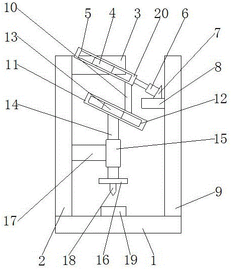
[0013] see figure 1 , the present invention provides a technical solution: an industrial equipment punching machine, including a base 1, the top of the base 1 is fixedly connected with a first support rod 2, and one side of the first support rod 2 is fixedly connected with a first support plate 3 , the front of the first support plate 3 is fixedly connected with the first slider 4, through the setting of the first support rod 2, the first slider 4 can be bette...


PUM


Abstract

The invention discloses an industrial equipment punching machine, comprising a base, the top of the base is fixedly connected with a first support rod, one side of the first support rod is fixedly connected with a first support plate, and the front of the first support plate is fixedly connected with a A first slider, the surface of the first slider is slidably connected to the first slot on the first slider, and one end of the first slider is fixedly connected to one end of the electric telescopic rod. In this industrial equipment punching machine, through the setting of the first slider, the first card slot and the electric telescopic rod, the first sliding plate can slide better, so that the connecting rod can drive the second sliding plate to slide, so that the punching needle can Moving up and down, this solves the situation that the punching machine cannot continue to punch holes, which improves the work efficiency, and the second sliding plate can move better through the setting of the second card slot and the second slider, so that the punching needle can realize Moving up and down, this new type of utility model has simple structure and low cost, making it easier for operators to get started.

Description

technical field [0001] The invention relates to the technical field of industrial equipment, in particular to an industrial equipment punching machine. Background technique [0002] Drilling machines are used in the processing and manufacturing of industrial equipment. At present, the industrial equipment punching machines on the market are all complex in structure, high in cost, and not easy to operate, which leads to many small enterprises not being able to purchase and use them in large quantities, and the existing industrial equipment punching machines on the market , Most of them are inefficient when punching holes, and continuous punching cannot be carried out, which reduces the efficiency of work. Contents of the invention [0003] The object of the present invention is to provide a punching machine for industrial equipment to solve the problems raised in the above-mentioned background technology. [0004] In order to achieve the above object, the present inventio...

Claims


Application Information

Patent Timeline
Patent Type & Authority Applications(China)
IPC IPC(8): B23B39/00B21D28/24
CPCB23B39/00B21D28/24
Inventor 陈婷
Owner 陈婷
Why Eureka
Try Eureka