
Anti-overflow robot

A robotic and anti-spill technology, applied in the field of robotics, can solve the problems of affecting meal delivery efficiency, large liquid sloshing, liquid overflow, etc., to reduce risks and slow down sudden fluctuations.

Pending Publication Date: 2017-06-13
GUANGDONG JATEN ROBOT & AUTOMATION
View PDF5 Cites 7 Cited by
  • Summary
  • Abstract
  • Description
  • Claims
  • Application Information

AI Technical Summary

Problems solved by technology

[0003] In particular, in the catering industry, there are more and more applications of robots. Currently, food delivery robots serving restaurants mainly use trays installed on the robot body to deliver dishes. When transporting liquids such as tea and coffee in cups, It is more difficult to drink, because this type of food delivery robot cannot overcome the problem of large liquid sloshing and even overflow caused by inertia during movement
Patent CN106333591A discloses a food delivery robot with a multi-functional tray. The tray of the robot is provided with compartments for placing water cups, drink grooves, etc., but this structure can only prevent the cup from tipping over. For cups without lids, it is still difficult to Keep drinks from spilling
Of course, in response to the above problems, food delivery can be completed by reducing the moving speed of the robot, or adding a cup cover to the delivered drink to prevent overflow, but because reducing the moving speed will affect the efficiency of food delivery, adding a cover will increase the transformation of existing containers. cost, so the above method cannot solve the problem of large liquid sloshing or liquid overflow, so it is necessary to develop a spill-proof robot

Method used


Image

  • Anti-overflow robot
  • Anti-overflow robot
  • Anti-overflow robot

Examples


Embodiment Construction

[0023] A preferred embodiment of the present invention will be described below with reference to the accompanying drawings.

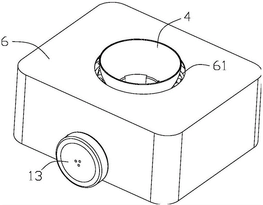
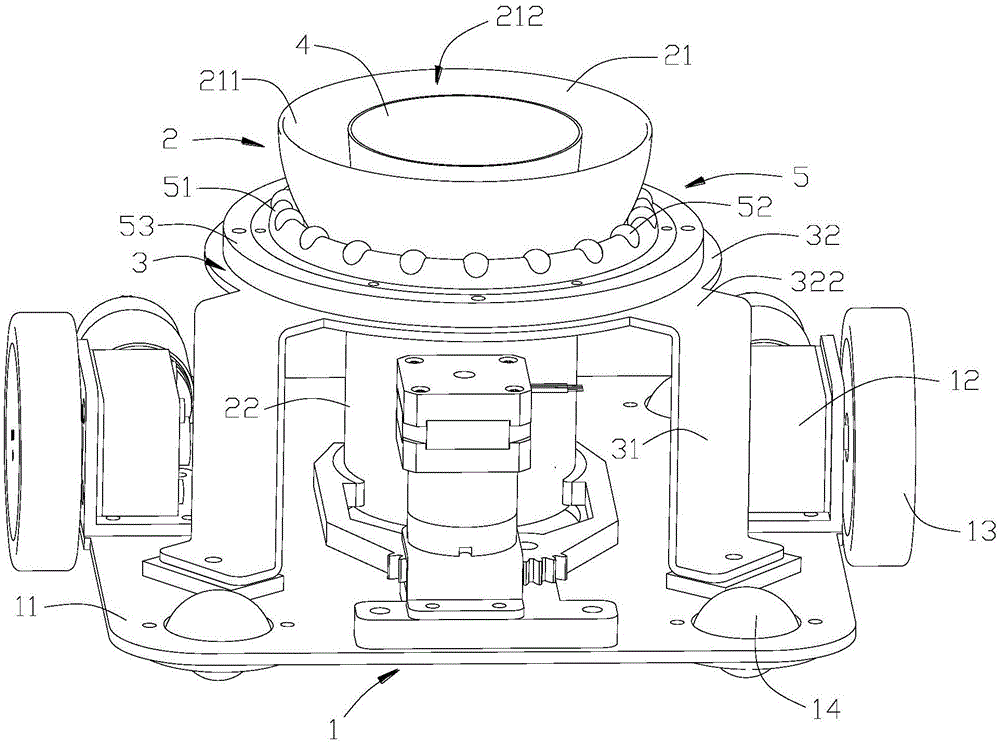
[0024] see figure 1 and figure 2 , an anti-overflow robot, including a housing 6, a mobile device 1, a cup holder 2 and a cup holder 3 arranged on the mobile device 1, the cup holder 3 is used to support the cup holder 2, and the housing 6 It is arranged on the outside of the cup holder 2 and the cup holder 3 , and the upper end is provided with a through hole 61 for the container 4 to pass through.

[0025] see figure 1 and Figure 5 , the mobile device 1 includes a chassis 11, the chassis 11 is provided with a driving mechanism, the driving mechanism includes two groups of servo motors 12, each group of servo motors 12 is connected with a driving wheel 13, the bottom side of the chassis 11 Several universal wheels 14 are provided, preferably four universal wheels 14 are evenly distributed at the corners of the chassis 11 . The output of the serv...


PUM


Abstract

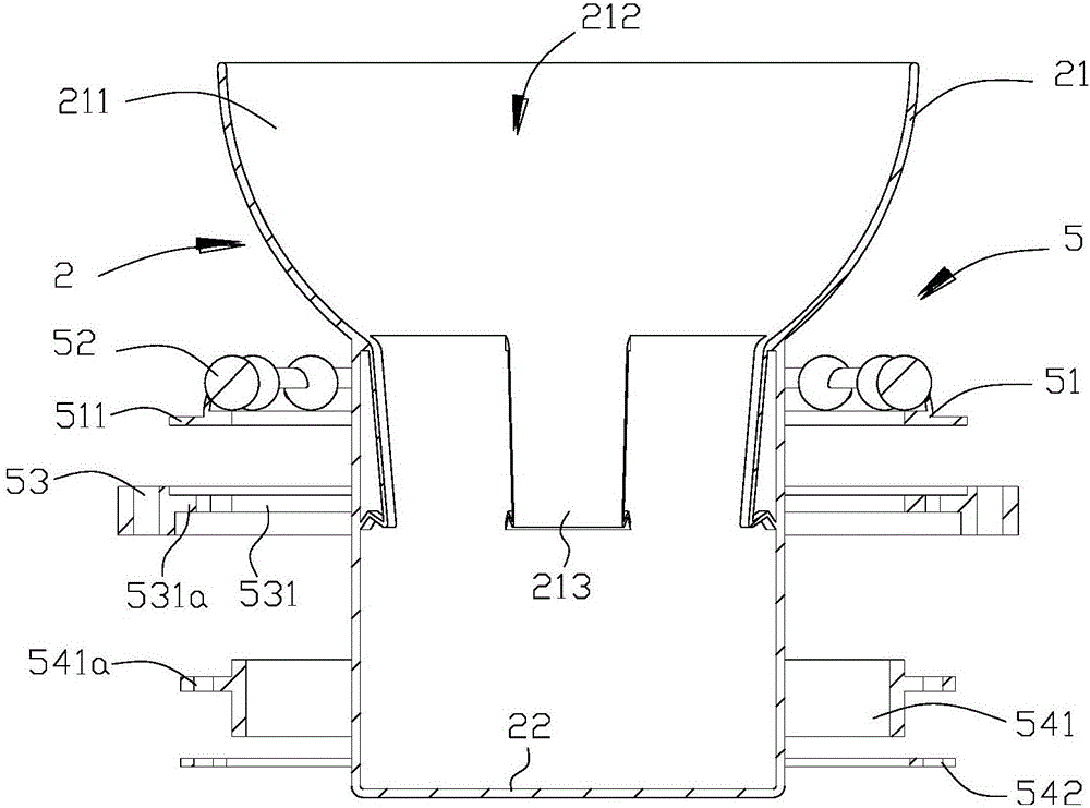
The invention belongs to the field of robots, and particularly relates to an anti-overflow robot. The anti-overflow robot comprises a mobile device, a cup base and a cup holder for bearing the cup base, wherein the mobile device comprises a base plate; the base plate is provided with a drive mechanism; the cup holder comprises a support part and a bearing part arranged at the upper end of the support part; the lower end of the support part is connected with the base plate; an installation hole through which the lower part of the cup base passes is formed in the bearing part; a rotating mechanism is also arranged on the bearing part; the cup base is arranged on the cup holder through the rotating mechanism; the upper part of the cup base is matched with the rotating mechanism, and the lower part of the cup base is inserted into the installation hole in the bearing part, so that the gravity center of the cup base is located at the lower part of the cup base; and the cup base can rotate relative to the cup holder through the rotating mechanism. Compared with the prior art, the anti-overflow robot is provided with the rotating mechanism and the cup base, and the cup base rotates at a certain angle through the rotating mechanism under the action of inertia, so that the anti-overflow robot plays a buffer role in shaking of liquid in a container, sudden fluctuation of the liquid level is avoided and the risk of overflow of the liquid is reduced.

Description

technical field [0001] The invention belongs to the field of robots, and in particular relates to an anti-overflow robot for transporting drinks. Background technique [0002] A robot is a machine device that performs work automatically. Because it can run pre-programmed programs to perform tasks, it can assist or replace people's work and is widely used in various fields. [0003] In particular, in the catering industry, there are more and more applications of robots. Currently, food delivery robots serving restaurants mainly use trays installed on the robot body to deliver dishes. When transporting liquids such as tea and coffee in cups, It is more difficult to drink, because this type of food delivery robot cannot overcome the problem of large liquid sloshing or even overflow caused by inertia during movement. Patent CN106333591A discloses a food delivery robot with a multi-functional tray. The tray of the robot is provided with compartments for placing water cups, drink...

Claims


Application Information

Patent Timeline
Patent Type & Authority Applications(China)
IPC IPC(8): B25J11/00B25J5/00
CPCB25J5/007B25J11/008
Inventor 陶茂林
Owner GUANGDONG JATEN ROBOT & AUTOMATION
Learn More