Anti-overflow control method of soybean milk machine

A control method and anti-overflow technology, which is applied in home appliances, applications, kitchen appliances, etc., can solve the problems of high heat generation, high speed, large load, etc., and achieve a reliable effect of the control scheme

Active Publication Date: 2017-11-17
JOYOUNG CO LTD
View PDF4 Cites 4 Cited by
  • Summary
  • Abstract
  • Description
  • Claims
  • Application Information

AI Technical Summary

Problems solved by technology

[0003] However, the motor with metal bearing seat fixed has higher speed, higher power and larger load, and generates a lot of heat, resulting in higher temperature of the motor, which is much higher than the slurry temperature. The heat and temperature of the motor are transmitted to the In the slurry, the temperature of the total slurry is raised during the beating process. Although the heating tube is not heated, a large amount of heat will still accumulate. During the beating process, the heat will expand outwards rapidly, resulting in the overflow of the slurry during the beating process.

Method used


Image

  • Anti-overflow control method of soybean milk machine
  • Anti-overflow control method of soybean milk machine
  • Anti-overflow control method of soybean milk machine

Examples


Embodiment 1

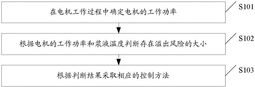
[0066] A kind of anti-overflow control method of soybean milk machine, such as image 3 As shown, the method may include S101-S103:

[0067] S101. Determine the working power of the motor during the working process of the motor.

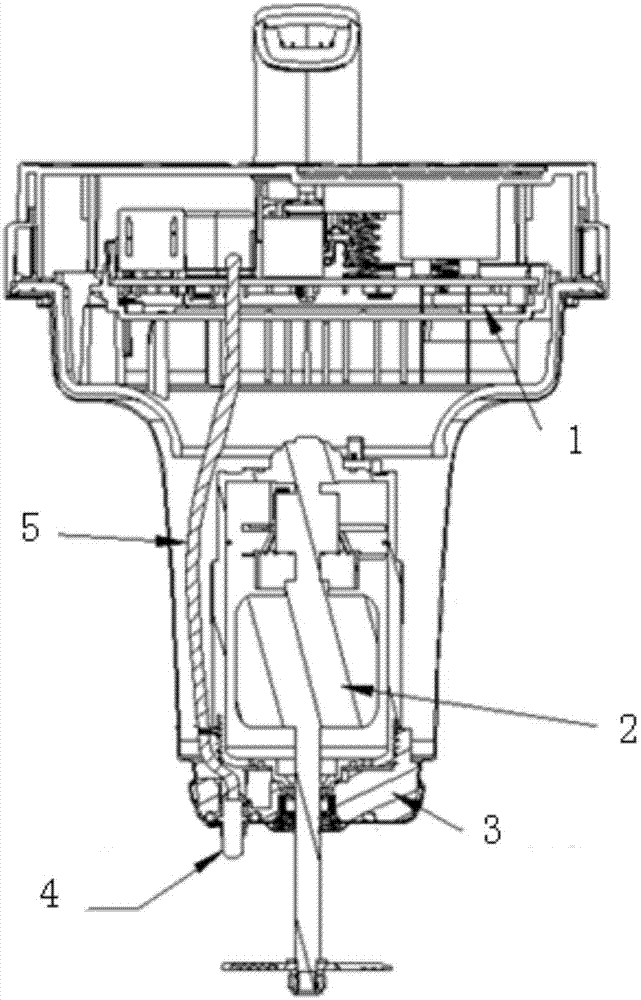
[0068] In the embodiment of the present invention, due to the many functions of the soybean milk machine, the recipes of different functions are quite different, the load difference of the motor during the beating process is also large, the working power of the motor is also large, and the heat generated is also large. The moment when the slurry temperature reaches a certain limit during the working process of the motor is also different. Therefore, it is necessary to monitor the working power of the motor during the working process of the motor to judge the risk of overflow according to the working power, so as to intelligently adjust the subsequent pulping process. Avoid overflow during the beating process.

[0069] In the embodiment of the prese...

Embodiment 2

[0103] The difference between this embodiment and the first embodiment is that another embodiment for judging the overflow risk is provided.

[0104] In the embodiment of the present invention, the change rate threshold value ΔV of the potential value of the temperature signal during the beating process can be preset. Accuracy and stability of temperature detection during beating process. Specifically, it can be realized through the following scheme.

[0105]Optionally, judging the degree of overflow risk based on the working power of the motor may also include:

[0106] calculating the slurry temperature change rate according to the detected slurry temperature and a preset first temperature threshold; and when the detected slurry temperature is greater than the first temperature threshold, updating the first temperature threshold with the detected slurry temperature;

[0107] When the slurry temperature change rate calculated for several times in succession is less than the...

Embodiment 3

[0112] This embodiment can intelligently identify the current working condition of the motor by detecting the number k of high-power beating temperature rises in the pulping process on the basis of the first or second embodiment.

[0113] Optionally, the method may also include:

[0114] counting the number of times the detected slurry temperature meets the second preset condition;

[0115] When the counted times meet the preset first count range, it is judged that the motor is currently in normal working state; when the counted counts meet the preset second count range, it is judged that the motor is currently in an overload working state; When the number of output times meets the preset third number range, it is determined that the motor is currently in a state of degraded performance;

[0116] Wherein, the number of times included in the range of the first number is less than the number of times included in the range of the second number; the number of times included in th...


PUM


Abstract

The embodiment of the invention discloses an anti-overflow control method of a soybean milk machine. The method includes the steps that the working power of a motor is determined in the working process of the motor; the probability of the overflow risk is judged according to the working power of the motor and the temperature of soybean milk; a corresponding control method is used according to a judgment result. By means of the method, the overflow risk in the working process of the motor can be intelligently judged, so that the phenomenon of overflowing during the soybean milk making process is avoided.

Description

technical field [0001] The embodiment of the present invention relates to the control technology of cooking equipment, in particular to an overflow prevention control method of a soybean milk machine. Background technique [0002] Such as figure 1 As shown, the current soybean milk machine includes an upper cover of the machine head, a lower cover of the machine head, a circuit board 1 (including the main control unit MCU) arranged on the upper cover of the machine head, a motor 2 and a fixed motor installed on the lower cover of the machine head The metal bearing seat 3 of 2, the temperature sensor 4 and the detection circuit are installed on the metal bearing seat 3, and the temperature sensor 4 is connected with the circuit board 1 through the signal line 5, such as figure 2 As shown, the detection circuit introduces the temperature sensor into the circuit board through the lead wire, and inputs it to the modulus AD detection port MCU_AD of the MCU through the pull-up r...

Claims


Application Information

Patent Timeline
Patent Type & Authority Applications(China)
IPC IPC(8): A47J43/07
CPCA47J43/0755
Inventor 王旭宁袁智辉郭明升汤立华
Owner JOYOUNG CO LTD
Why Eureka
Try Eureka