An expansion tank and a fuel cell thermal management system

A technology of expansion tank and tank body, which is applied in the directions of fuel cell heat exchange, fuel cell, fuel cell auxiliary, etc. The effect of saving the replacement time

Pending Publication Date: 2018-12-21
SHANGHAI CHONGSU ENERGY TECH CO LTD
View PDF3 Cites 7 Cited by
  • Summary
  • Abstract
  • Description
  • Claims
  • Application Information

AI Technical Summary

Problems solved by technology

[0004] The purpose of this application is to provide an expansion tank to solve the problems in the prior art that the deionizer is arranged outside the expansion tank, resulting in a large volume and low integration of the fuel cell system

Method used


Image

  • An expansion tank and a fuel cell thermal management system
  • An expansion tank and a fuel cell thermal management system
  • An expansion tank and a fuel cell thermal management system

Examples


Embodiment Construction

[0026] In order to make the purpose, advantages and features of the application clearer, the following in conjunction with the attached Figure 1-9 The expansion tank proposed in this application will be further described in detail. It should be noted that the drawings are all in very simplified form and use imprecise scales, and are only used to facilitate and clearly assist the purpose of illustrating the embodiments of the present application.

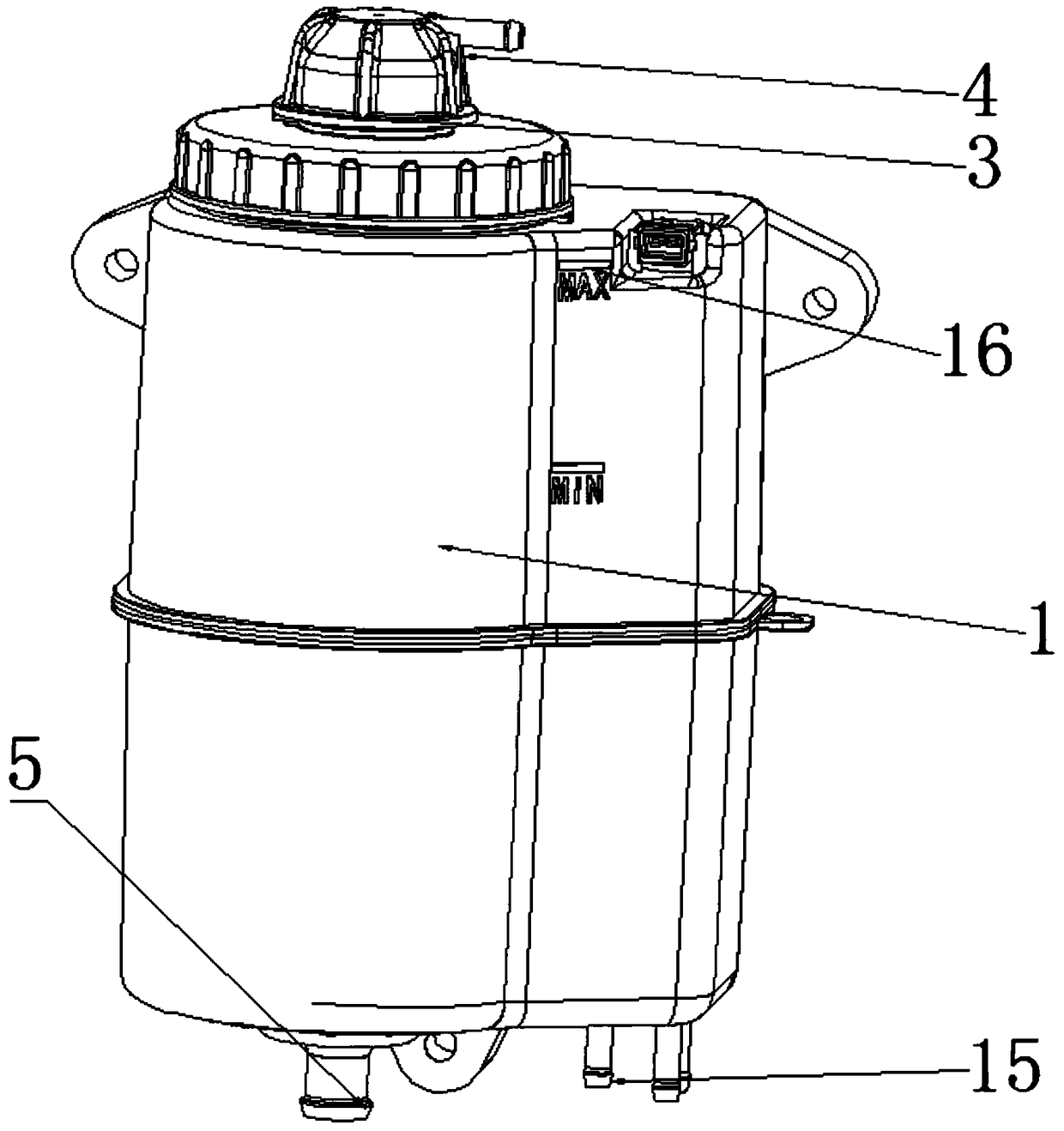
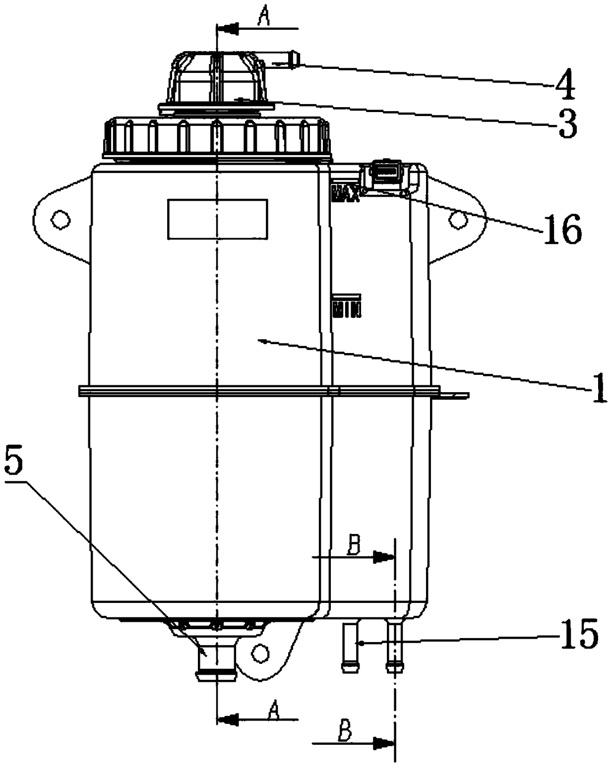
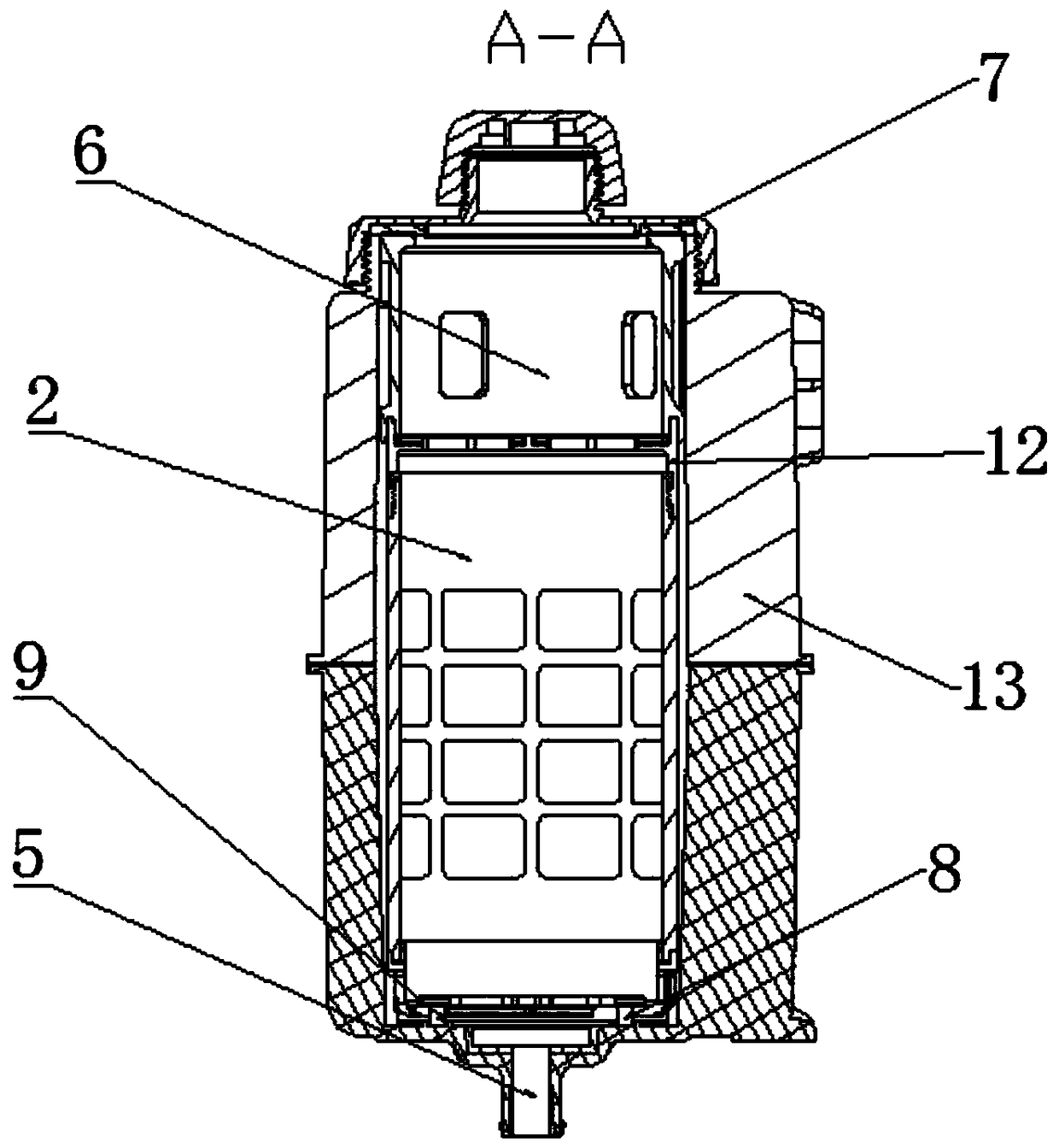
[0027] figure 1 It is a perspective view of the expansion tank of the embodiment of the present application; figure 2 is the front view of the expansion tank of the embodiment of the present application; image 3 yes figure 2 Sectional view of A-A in Fig.

[0028] refer to Figure 1-3 , the application provides an expansion tank, including a rectangular parallelepiped tank body 1 and a deionizer 2 set up vertically; The description is as follows: according to the needs of the working environment, the tank body 1 can be desig...


PUM

PropertyMeasurementUnit
diameteraaaaaaaaaa
diameteraaaaaaaaaa

Abstract

An expansion tank provided by the present application reduces the volume occupied by a fuel cell system and improves the integration level by arranging a deionizer in the tank body. At the same time,since the deionizer is integrated in the expansion tank, when replacing the deionizer, it is not necessary to completely drain the coolant in the system, thereby saving the replacing time. Further, the tank body is provided with an overflow pipe opening, which can ensure that the coolant pressure is controllable and can be balanced with the pressure of air and hydrogen on both sides; The expansiontank can effectively solve the problem that the coolant overflows into the expansion tank when the water pump stops suddenly, ensure that the coolant of the fuel cell is not polluted, and ensure thesafety of the fuel cell operation and the like.

Description

technical field [0001] The present application relates to the technical field of fuel cells, in particular to an expansion tank and a fuel cell thermal management system. Background technique [0002] Due to the particularity of the fuel cell, the conductivity of the coolant in the fuel cell system is required to be less than 5 μs / cm. In the thermal management system of the fuel cell system, the commonly used tube-and-belt radiators, PTCs, air compressors and other components will lead to an increase in the conductivity of the coolant. In addition, due to the small size of the deionized resin particles, the flow resistance is relatively large. How to effectively reduce the conductivity of the coolant in the thermal management system and how to reduce the influence of the flow resistance of the deionizer on the flow of the system are difficult problems to be solved by the fuel cell thermal management system. [0003] In the prior art, the deionizer is installed outside the ...

Claims


Application Information

Patent Timeline
Patent Type & Authority Applications(China)
IPC IPC(8): H01M8/04007H01M8/04029
CPCH01M8/04029H01M8/04067Y02E60/50
Inventor 王银龙柯小军刘德华狄鑫
Owner SHANGHAI CHONGSU ENERGY TECH CO LTD
Why Eureka
Try Eureka