Developing roller used in laser printer

A technology of laser printers and developing rollers, applied in optics, electrical recording technology using charge graphics, equipment using electrical recording technology using charge graphics, etc., can solve problems such as reducing sealing structure, deformation of aluminum tubes, and reducing transmission torque , to achieve the effect of reducing torque, stable quality and reducing the risk of powder leakage

Inactive Publication Date: 2013-08-14
ZHUHAI BENMA PRINTMAX IMAGINE
View PDF7 Cites 4 Cited by
  • Summary
  • Abstract
  • Description
  • Claims
  • Application Information

AI Technical Summary

Problems solved by technology

[0005] In order to overcome the deficiencies of the prior art, the present invention provides a new development roller in laser printers, through which the transmission torque can be greatly reduced, the se

Method used


Image

  • Developing roller used in laser printer
  • Developing roller used in laser printer
  • Developing roller used in laser printer

Examples


Embodiment Construction

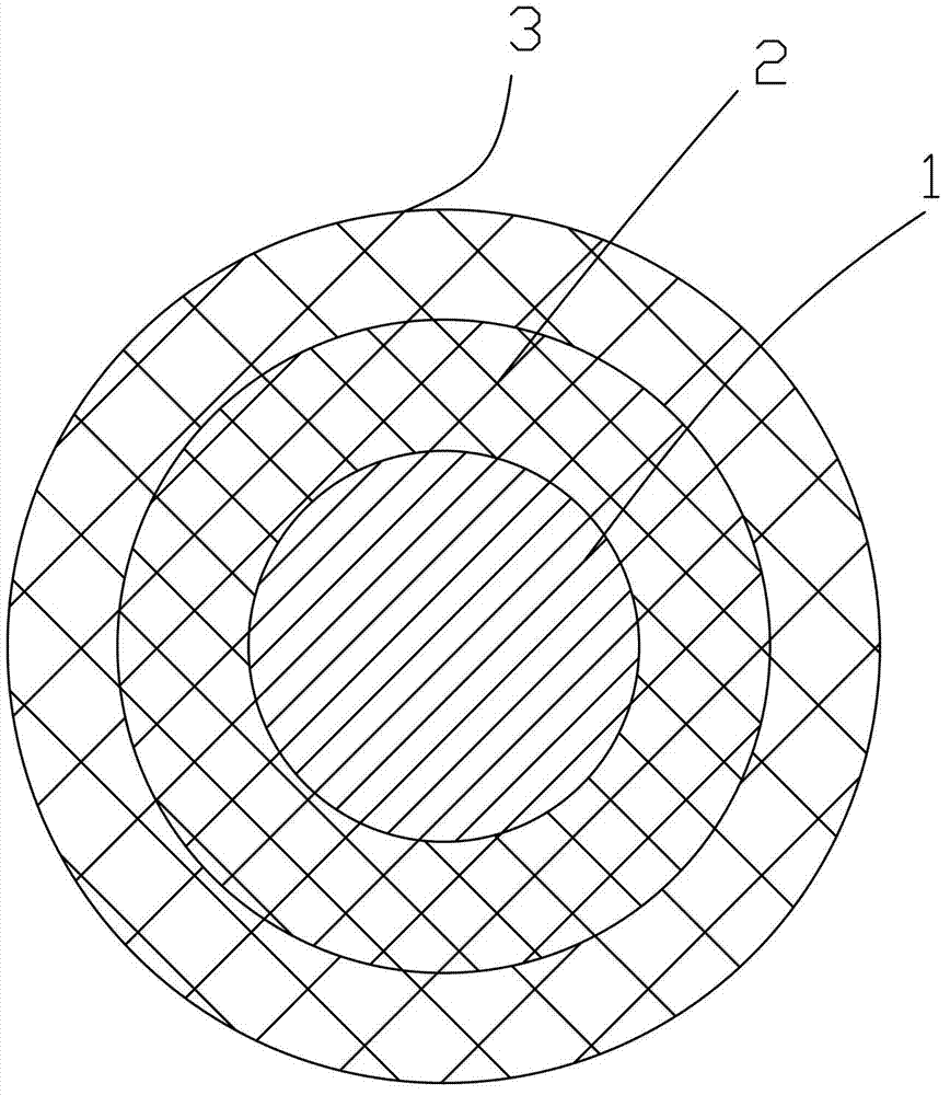
[0020] The invention discloses a developing roller in a laser printer, which comprises a magnetic core. The magnetic core includes a metal shaft core 1 and a magnetic layer 2 fixed on the metal shaft core 1. Several magnetic poles are arranged on the magnetic layer 2. The magnetic core An elastic body layer 3 made of conductive material is wrapped on it, and the metal shaft core 1 is electrically connected with the elastic body layer 3 .

[0021] refer to figure 1 , figure 1 It is a cross-sectional view of Embodiment 1 of the present invention, in which the middle core is a metal round roller as the metal shaft core 1 of the developing roller, which is used to carry the remaining parts of the developing roller and make the rest of the parts together with the metal shaft core 1 Rotation; the metal shaft core 1 is preferably steel, and of course other metals, such as aluminum, copper, etc., the metal shaft core 1 is covered with a magnetic layer 2, and the magnetic layer 2 is i...


PUM

PropertyMeasurementUnit
Volume resistivityaaaaaaaaaa
Thicknessaaaaaaaaaa
Magnetic inductionaaaaaaaaaa

Abstract

The invention discloses a developing roller used in a laser printer. The developing roller comprises a magnetic core, wherein the magnetic core comprises a metal shaft core and a magnetic layer fixed on the metal shaft core, wherein a plurality of magnetic poles are arranged on the magnetic layer, an elastomer layer made of a conducting material is wrapped on the magnetic layer, and the metal shaft core is electrically connected with the elastomer layer. As the magnetic poles are additionally arranged inside the traditional rubber developing roller, the surface of the elastomer layer has certain magnetic field intensity, the magnetic single-component carbon powder is absorbed onto the surface of the elastomer layer of the developing roller and does not need to be fed through a powder feeding roller, the rolling torque is further reduced, and on the other side, the magnetic field force acted to the carbon powder is favorable for sealing powder, and therefore, the risk of powder leakage is greatly reduced; and compared with the developing roller with the elastomer layer wrapped outside the aluminum tube of the magnetic roller, the process requires that a rubber layer with thickness being smaller than 2mm is wrapped outside the thin-walled aluminum tube with thickness being about 0.8-1.5mm, the process is extremely difficult, and the aluminum tube is easily deformed during the transmission process to cause quality problems.

Description

technical field [0001] The invention relates to a developing roller, in particular to a developing roller in a laser printer. Background technique [0002] In the existing laser printing technology, there are two types according to the method: one is the contact developing method, and the other is the non-contact developing method. [0003] The working principle of the contact developing method is: the developing roller is mostly a metal core rubber roller, which has a large volume resistance. The photosensitive drum directly contacts the developing roller, and the charged toner on the developing roller is absorbed by the electric field force in the graphic area to develop the image. ,This method must have a porous powder feeding roller in contact with the developing roller, so the torque is large, and because the toner is not subjected to magnetic force, it is easy to dislodge from the developing roller during the transfer of the toner from the powder bin to the photosensit...

Claims


Application Information

Patent Timeline
IPC IPC(8): G03G15/09
CPCG03G15/0928
Inventor 曹国柱
Owner ZHUHAI BENMA PRINTMAX IMAGINE
Why Eureka
Try Eureka