Computer numerical control saw

An electronic cutting saw and saw blade technology, which is applied in the direction of circular saws, sawing components, sawing equipment, etc., can solve the problems of single thickness and the height of the saw blade cannot rise and fall with the thickness of the plate, and achieve the effect of improving efficiency

Inactive Publication Date: 2017-06-13
SICHUAN HENGXIN YOUBANG FURNITURE CO LTD
View PDF9 Cites 10 Cited by
  • Summary
  • Abstract
  • Description
  • Claims
  • Application Information

AI Technical Summary

Problems solved by technology

[0004] The purpose of the present invention is to solve the problem that the thickness of the workpiece to be cut is single in the above cutting saw equipment, and the height of the saw blade cannot rise and fall with the thickness of the plate. The present invention proposes an electronic cutting equipment

Method used


Image

  • Computer numerical control saw
  • Computer numerical control saw

Examples


Embodiment 1

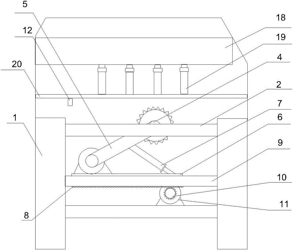
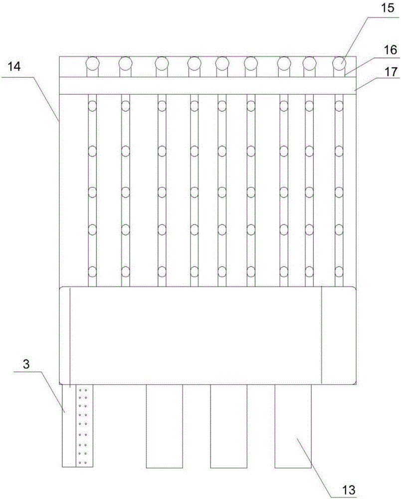
[0025] An electronic cutting saw, comprising a frame 1, a workbench 2 arranged on the frame 1, and an electric control cabinet 3, the frame 1 is provided with a mounting beam 9, and the lower side of the workbench 2 is provided with a saw blade drive system, the saw blade drive system includes a saw blade drive motor 4, the saw blade drive motor 4 is connected to the connecting rod 5, the connecting rod 5 is hinged on the saw blade support platform 6, the middle part of the connecting rod is connected to the side thrust cylinder 7, and the saw blade is supported A rack 8 is arranged on the platform, and rollers are arranged parallelly on both sides of the saw blade support platform 6. The saw blade support platform 6 is arranged on the installation beam 9, and the installation beam 9 is provided with sliding tracks corresponding to the rollers; the saw blade supports The rack 8 of the table 6 meshes with the gear 11 of the displacement motor 10 ; a distance sensor 12 is provide...

Embodiment 2

[0027] An electronic cutting saw, comprising a frame 1, a workbench 2 arranged on the frame 1, and an electric control cabinet 3, the frame 1 is provided with a mounting beam 9, and the lower side of the workbench 2 is provided with a saw blade drive system, the saw blade drive system includes a saw blade drive motor 4, the saw blade drive motor 4 is connected to the connecting rod 5, the connecting rod 5 is hinged on the saw blade support platform 6, the middle part of the connecting rod is connected to the side thrust cylinder 7, and the saw blade is supported A rack 8 is arranged on the platform, and rollers are arranged parallelly on both sides of the saw blade support platform 6. The saw blade support platform 6 is arranged on the installation beam 9, and the installation beam 9 is provided with sliding tracks corresponding to the rollers; the saw blade supports The rack 8 of the table 6 meshes with the gear 11 of the displacement motor 10 ; a distance sensor 12 is provide...

Embodiment 3

[0030] An electronic cutting saw, comprising a frame 1, a workbench 2 arranged on the frame 1, and an electric control cabinet 3, the frame 1 is provided with a mounting beam 9, and the lower side of the workbench 2 is provided with a saw blade drive system, the saw blade drive system includes a saw blade drive motor 4, the saw blade drive motor 4 is connected to the connecting rod 5, the connecting rod 5 is hinged on the saw blade support platform 6, the middle part of the connecting rod is connected to the side thrust cylinder 7, and the saw blade is supported A rack 8 is arranged on the platform, and rollers are arranged parallelly on both sides of the saw blade support platform 6. The saw blade support platform 6 is arranged on the installation beam 9, and the installation beam 9 is provided with sliding tracks corresponding to the rollers; the saw blade supports The rack 8 of the table 6 meshes with the gear 11 of the displacement motor 10 ; a distance sensor 12 is provide...


PUM


Abstract

The invention relates to a computer numerical control saw which comprises a frame, a working table, an electric control cabinet, wherein the working table and the electric control cabinet are arranged on the frame. A saw blade driving system, a device capable of detecting the height of feeding materials and a device capable adjusting the height of a saw blade are arranged on the frame of the computer numerical control saw, the saw blade driving system can push the saw blade to move and comprises a saw blade driving motor, the saw blade driving motor is connected with a connecting rod, the connecting rod is hinged onto a motor mounting platform, a side push cylinder is connected in the middle of the connecting rod, a rack is arranged below the motor mounting platform, rollers are parallelly arranged on two sides of the motor mounting platform, the motor mounting platform is arranged on a motor mounting beam, and sliding rails corresponding to the rollers are arranged on the motor mounting beam. The system can drive the saw blade to linearly move in a reciprocating manner, rise and fall, so that saw cutting actions are finished, and the height of the saw blade is adjusted.

Description

technical field [0001] The invention relates to the field of furniture processing equipment, in particular to an electronic cutting saw. Background technique [0002] In the process of furniture manufacturing and processing, when processing boards, wood is often sawed by manual sawing. In the process of manually sawing wood, the cutting saw used is mainly a sliding table saw. Since the sliding table saw can only be used alone, the plate needs to be fixed for processing during use, and manpower is also required to reciprocate push and pull. This processing method is time-consuming, laborious and inefficient. [0003] At present, there are also some cutting saw equipment for processing boards. When these devices reprocess wood, because the height of the saw blade is fixed, when sawing, the thickness of the boards to be sawed is very limited, and the boards to be sawed each time cannot exceed a certain amount. Thickness, therefore, also results in less efficient sawing. Con...

Claims


Application Information

Patent Timeline
Patent Type & Authority Applications(China)
IPC IPC(8): B27B5/02B27B5/20B27B5/29B27B25/00
CPCB27B5/02B27B5/202B27B5/208B27B5/29B27B25/00
Inventor 黄智罗继松王祝
Owner SICHUAN HENGXIN YOUBANG FURNITURE CO LTD
Why Eureka
Try Eureka