Self-adaptation controllable vibration metal cutting device and method based on super magnetostriction

A giant magnetostrictive and metal cutting technology, which is applied in the attachments of sawing machines, metal sawing equipment, sawing machine devices, etc. It is difficult to ensure the accuracy of the vibration mechanism and other problems, so as to improve the cooling effect, improve the sawing efficiency, and increase the output power.

Pending Publication Date: 2019-03-01
LISHUI UNIV
View PDF0 Cites 3 Cited by
  • Summary
  • Abstract
  • Description
  • Claims
  • Application Information

AI Technical Summary

Problems solved by technology

Although some researchers have carried out some research on vibration sawing, the structural design of the vibration device is too complicated, and it is difficult to ensure the accuracy of the vibration amplitude and vibration frequency of the vibration mechanism. In addition, the vibration amplitude and vibration frequency of the vibration device mentioned It is also impossible to produce adaptive real-time adjustments according to the material of the sawing material. The above factors will directly affect the processing efficiency of sawing and the sawing quality of the processed workpiece.

Method used


Image

  • Self-adaptation controllable vibration metal cutting device and method based on super magnetostriction
  • Self-adaptation controllable vibration metal cutting device and method based on super magnetostriction
  • Self-adaptation controllable vibration metal cutting device and method based on super magnetostriction

Examples


Embodiment Construction

[0031] The present invention will be described in further detail below in conjunction with the accompanying drawings and specific embodiments.

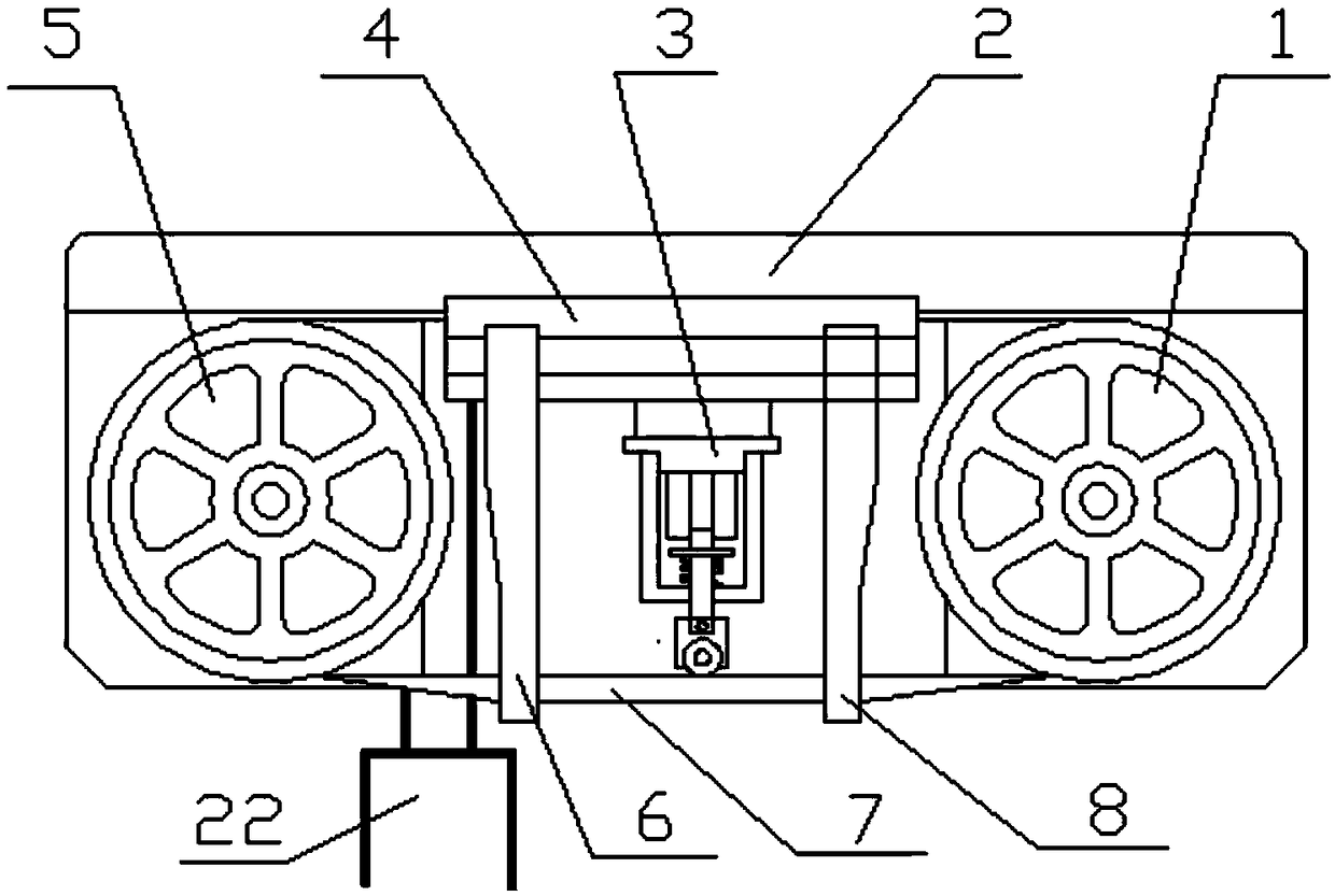
[0032] Such as figure 1 As shown, a driving pulley 1 and a driven pulley 5 are installed on both sides of the saw frame 2 respectively, and a conveyor belt is set on the driving pulley 1 and the driven pulley 5, and a saw blade 7 is installed on the outside of the conveyor belt. A vibration mechanism 3 and a saw beam 4 are installed between the moving pulleys 5, the saw beam 4 is fixed on the saw frame 2, the upper end of the vibration mechanism 3 is fixed on the middle part of the lower end surface of the saw beam 4, and the lower end of the vibration mechanism 3 is connected to the saw blade 7 located below. The back is in rolling contact; the two sides of the vibrating mechanism 3 are respectively provided with a left guide arm 6 and a right guide arm 8, and the upper ends of the left and right guide arms 6, 8 are respectively fixe...


PUM


Abstract

The invention discloses a self-adaptation controllable vibration metal cutting device and method based on super magnetostriction. A saw frame, a vibration mechanism, a saw beam, a driving belt wheel,a driven belt wheel, a saw strip, a hydraulic cylinder and a DSP chip are included. The vibration mechanism is fixed to the lower end face of the saw beam. A left guiding arm and a right guiding arm are arranged on the two sides of the vibration mechanism correspondingly. The base is arranged at the opening position in the upper end of the shell. The lower end face of the base is connected with anamplitude changing rod through a super magnetostriction material. The amplitude changing rod penetrates through the bottom face of the shell and is connected with a bearing frame. The outer side faceof the super magnetostriction material is sequentially sleeved with an exciting coil and a permanent magnet. The driven belt wheel and the driving belt wheel are provided with a rotation speed sensorand a torque sensor correspondingly. The rotation speed sensor and the torque sensor are connected with the DSP chip. The DSP chip is connected with the vibration mechanism through a PLC. Through thesimple structure design, saw strip vibration cutting can be achieved, saw strip tooth tips can more easily cut into the materials, and cuttings can be more easily discharged.

Description

technical field [0001] The invention relates to a metal cutting device and method, in particular to an adaptive controllable vibration metal cutting device and method based on giant magnetostriction. Background technique [0002] As the main equipment in the blanking process, metal cutting band sawing machines have been widely used in various fields such as automobiles, shipbuilding, and aerospace. As the modern manufacturing industry is developing towards high efficiency and high precision, the industrial field has put forward an urgent demand for the improvement of the sawing efficiency of metal band sawing machines, especially the improvement of the cutting efficiency of hard metals has always been the focus of attention. The traditional sawing method is to continuously feed the saw blade downward during the sawing process, and use the rapid movement of the sawtooth to realize the function of cutting metal. Since the saw blade itself is less rigid, it cannot guarantee tha...

Claims


Application Information

Patent Timeline
Patent Type & Authority Applications(China)
IPC IPC(8): B23D53/00B23D55/00B23D59/00
CPCB23D53/00B23D55/00B23D59/00
Inventor 周红明
Owner LISHUI UNIV
Why Eureka
Try Eureka