Multi-power source decoupling and vector controlling device and method for gasoline-electric hybrid unmanned gyroplane

A technology of unmanned rotor and vector control, which is applied to power plants, motor vehicles, unmanned aircraft, etc. on aircraft, can solve the problems of slow flight speed, stalling, and inability to achieve fast flight, etc., to achieve increased flight speed, The effect of stable flight

Inactive Publication Date: 2017-06-13
中国人民解放军防空兵学院
View PDF5 Cites 8 Cited by
  • Summary
  • Abstract
  • Description
  • Claims
  • Application Information

AI Technical Summary

Problems solved by technology

However, the oil-electric hybrid rotor UAV with this structure has a slow flight speed due to the decoupling of multiple power sources and the vector control device, and it is difficult to achieve fast flight.
This is because both the motor and the engine provide forward flight power for the UAV during the fast flight, and the two different forms of power sources are coupled together. In order to overcome the resistance, a larger forward angle will appear, and a larger forward angle The speed of the motor in the direction of the nose will become very low, or even stop. When encountering disturbances such as wind, the front motor will lose its ability to adjust, and the drone will shake a lot, or even crash, so it is impossible to achieve fast speed. Flying, wind resistance is also poor

Method used


Image

  • Multi-power source decoupling and vector controlling device and method for gasoline-electric hybrid unmanned gyroplane
  • Multi-power source decoupling and vector controlling device and method for gasoline-electric hybrid unmanned gyroplane
  • Multi-power source decoupling and vector controlling device and method for gasoline-electric hybrid unmanned gyroplane

Examples


Embodiment Construction

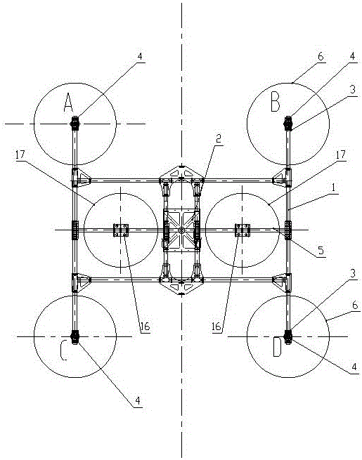
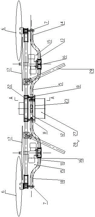
[0040] Such as figure 1 , 2 As shown in . The central platform 2 of the frame at the position, and the UAV frame 1 is provided with an even number of arms 3, figure 1 The embodiment in is a multi-rotor UAV with a four-axis "X" configuration. Four arms 3 are arranged on the frame 1 of the UAV. Each arm 3 is connected to a motor 4, and each motor 4 is connected to There are 6 motor propellers. Also be connected with landing support 29 on the UAV frame 1.

[0041] Four T-motor u11 motors are selected and equipped with 28-inch carbon fiber propellers. If the take-off weight is 47kg, the pulling force generated at 50% throttle is about 22kg.

[0042] The rotor drone of the present invention also includes a gasoline power vector shaft 5, the left and right ends of the gasoline power vector shaft 5 are rotationally connected with the UAV frame 1, and the two ends of the gasoline power vector shaft 5 are connected to the UAV frame 1. An end bearing 7 is provided, and the middle p...


PUM


Abstract

Disclosed is a multi-power source decoupling and vector controlling device for a gasoline-electric hybrid unmanned gyroplane. The unmanned gyroplane comprises a gyroplane frame, a gasoline power vector revolving shaft and a gasoline power vector control device. The gyroplane frame is provided with a frame center platform at the center; the frame center platform comprises an upper center plate and a lower center plate which are arranged in parallel and at an interval. Arms of the gyroplane frame are provided with motors; two oil-driven engines are installed on the gyroplane frame, and the oil-driven engines refer to gasoline piston type engines. Both the motors and the oil-driven engines are provided with propellers. Two ends of the gasoline power vector revolving shaft are connected with the unmanned gyroplane frame rotationally; end bearings are arranged at positions between two ends of the gasoline power vector revolving shaft and the unmanned gyroplane frame. The multi-power source decoupling and vector controlling device has the advantages that high-speed stable flight of the unmanned gyroplane is realized, and problems that a part of the motors are stopped and adjusting capacity is lost due to large top rake during quick flight of the conventional electric unmanned vehicles and the conventional oil-electric hybrid uumanned gyroplanes, and the conventional unmanned vehicles shakes violently and even crash when fly in gust or slowing down to fly are solved.

Description

technical field [0001] The invention relates to the field of unmanned aerial vehicles, in particular to an oil-electric hybrid multi-rotor unmanned aerial vehicle. Background technique [0002] The multi-rotor UAV has simple structure, low cost, and easy operation. It has been widely used in aerial photography, surveying and mapping, agricultural plant protection and other fields. However, due to the limited energy density of lithium batteries, the endurance time and load capacity of pure rotor drones are extremely limited, which limits its application in the industrial field. For this reason, many engineers and technicians combine small aviation piston engines with rotor drones. , install the engine vertically on the multi-rotor drone, and the oil-driven part provides part of the upward pulling force for the drone. By installing spoilers on the arm or flying the multi-rotor drone, the structure is simple, the cost is low, and the control is easy. It has been widely used in...

Claims


Application Information

Patent Timeline
Patent Type & Authority Applications(China)
IPC IPC(8): B64D27/02B64D31/00
CPCB64D27/02B64D31/00B64D2027/026B64U50/11B64U10/10B64U50/19
Inventor 胡延霖苏永振孟祥忠易牧陈永明孙遥董岩王小念
Owner 中国人民解放军防空兵学院
Why Eureka
Try Eureka