Supercharge Your Innovation With Domain-Expert AI Agents!

Conveying device and conveying line body thereof

A technology of conveying device and conveying mechanism, which is applied in the direction of conveyor control device, conveyor, mechanical conveyor, etc., can solve the problems of real-time control of product flow or stop by conveyor belt, increase production cost, and produce defective products, etc. To achieve the effect of reducing the use of labor, reducing collisions, and improving the pass rate

Pending Publication Date: 2017-06-13
东莞松山智能机器人有限公司
View PDF7 Cites 9 Cited by
  • Summary
  • Abstract
  • Description
  • Claims
  • Application Information

AI Technical Summary

Problems solved by technology

[0002] In the production process, it is an indispensable link in the production process to use the conveyor belt to transport the workpiece to different positions for different processes. The characteristics of the traditional conveyor belt are: the conveying speed is constant during the conveying process. When the speed of the workpiece at the end of the conveyor belt is lower than the conveying speed of the conveyor belt, more and more workpieces are gathered at the end of the conveyor belt. Therefore, the current conveyor belt cannot control the state of product flow or stop in real time according to the characteristics of the workpiece. The collision between them will also produce defective products, which will bring unnecessary losses to production and increase production costs.

Method used


Image

  • Conveying device and conveying line body thereof
  • Conveying device and conveying line body thereof
  • Conveying device and conveying line body thereof

Examples


Embodiment Construction

[0038] In order to facilitate the understanding of those skilled in the art, the present invention will be further described below in conjunction with the embodiments and accompanying drawings, and the contents mentioned in the implementation modes are not intended to limit the present invention.

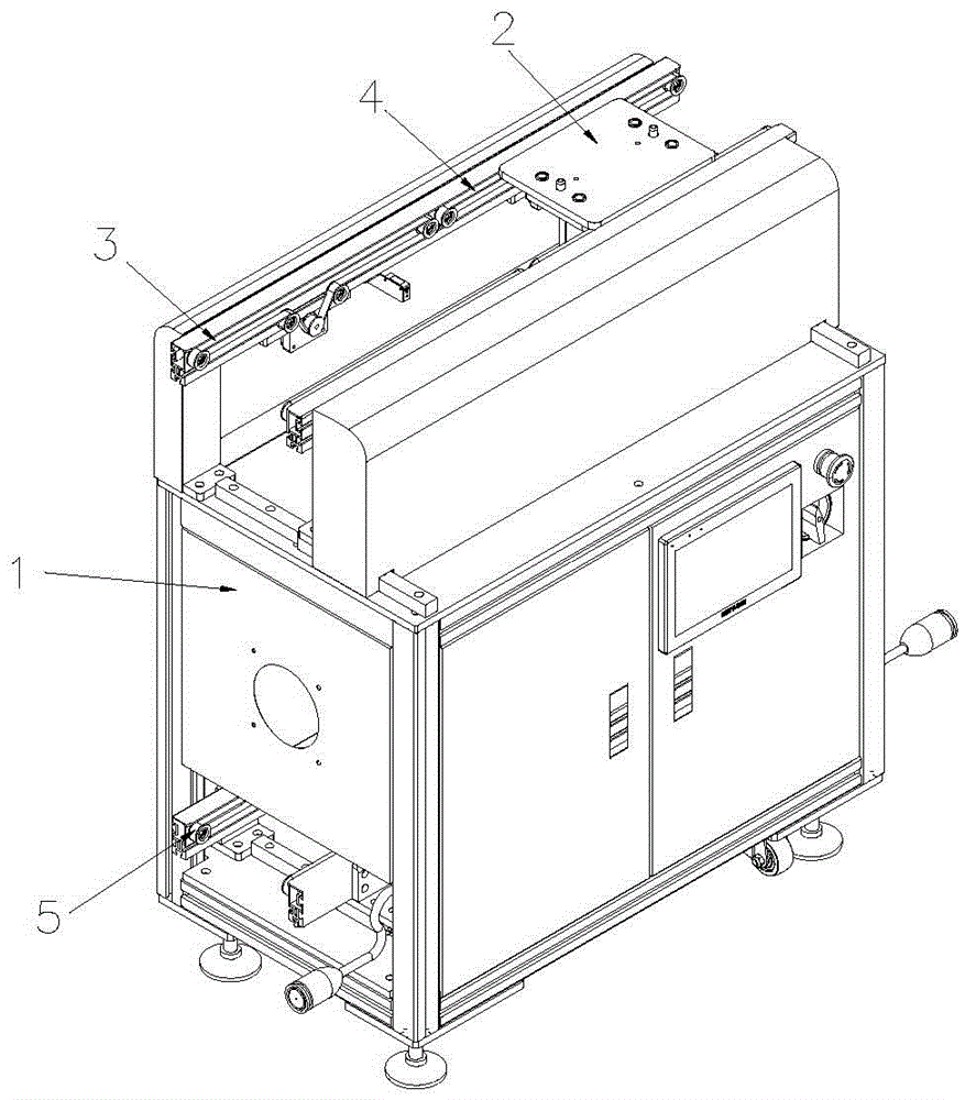
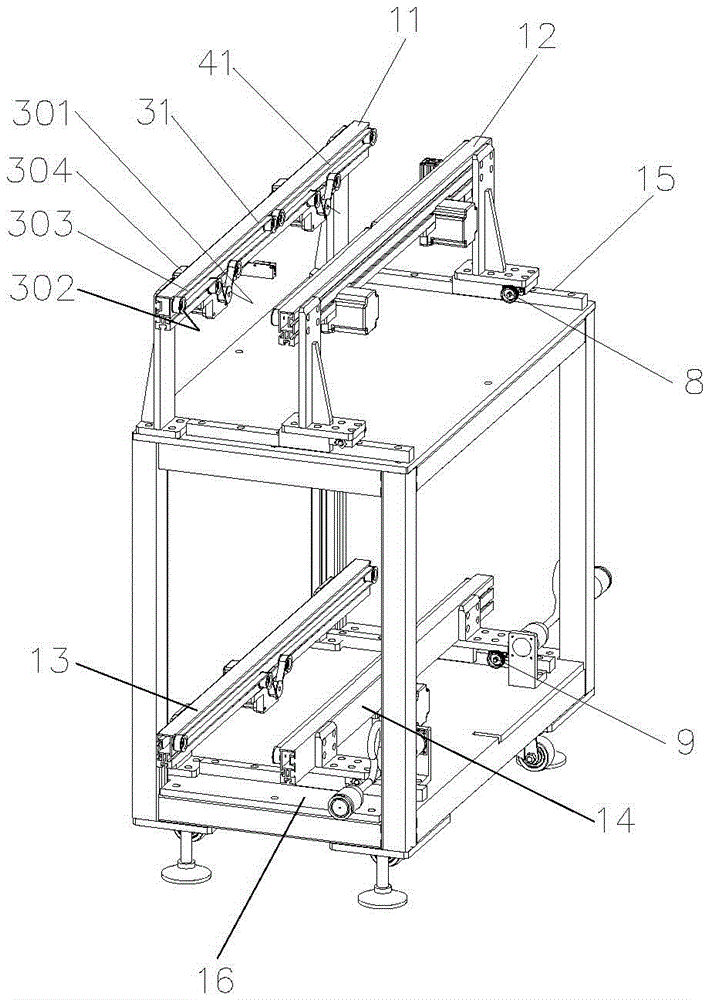
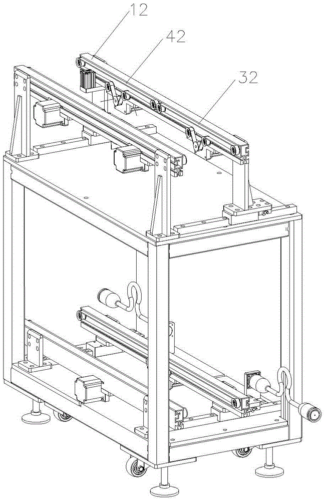
[0039] A conveying device of the present invention includes a frame 1, and at least one conveying device for conveying loading boards. The conveying device includes a front conveying mechanism 3 and a rear conveying mechanism 4 docked with the front conveying mechanism 3. The preceding section conveying mechanism 3 includes a first conveying mechanism 31 and a second conveying mechanism 32 arranged on the support 1, and the first conveying mechanism 31 and the second conveying mechanism 32 all include a first driving pulley 301, a first slave Driving pulley 302, the first motor 303 for driving the first driving pulley 301 to rotate and the first synchronous belt 304 connecting the fi...


PUM


Abstract

The invention relates to the technical field of production conveying equipment and particularly discloses a conveying device and a conveying line body thereof. The conveying device comprises a rack and further comprises at least one conveying device body used for conveying loading plates. Each conveying device body comprises a front section conveying mechanism and a rear section conveying mechanism connected with the front section conveying mechanism in a butt joint mode. Each front section conveying mechanism comprises a first conveying mechanism and a second conveying mechanism which are used for carrying the loading plates. Each rear section conveying mechanism comprises a third conveying mechanism and a fourth conveying mechanism. The structures of the conveying mechanisms are all consistent. The conveying device has the beneficial effects that the loading plates loaded with workpieces are placed on conveying lines provided with the two section conveying mechanisms, so that different speeds of conversion in the conveying process is achieved; the speeds of the workpieces on the conveying lines can be better adjusted; the phenomenon of collision among the workpieces is reduced; the situation that a defective product is produced due to the collision is avoided; the qualification rate of workpiece machining is increased; the production cost is reduced; and the working efficiency is improved.

Description

technical field [0001] The invention relates to the technical field of generating conveying equipment, and in particular discloses a conveying device and a conveying line body thereof. Background technique [0002] In the production process, it is an indispensable link in the production process to use the conveyor belt to transport the workpiece to different positions for different processes. The characteristics of the traditional conveyor belt are: the conveying speed is constant during the conveying process. When the speed of the workpiece at the end of the conveyor belt is lower than the conveying speed of the conveyor belt, more and more workpieces are gathered at the end of the conveyor belt. Therefore, the current conveyor belt cannot control the state of product flow or stop in real time according to the characteristics of the workpiece. The collision between them will also produce defective products, which will bring unnecessary losses to production and increase prod...

Claims


Application Information

Patent Timeline
IPC IPC(8): B65G47/88B65G43/08B65G37/02B65G15/20B65G47/31B65G47/22
CPCB65G15/20B65G37/02B65G43/08B65G47/22B65G47/31B65G47/8815
Inventor 杨司再黄水灵彭心宽王善平
Owner 东莞松山智能机器人有限公司
Features
  • R&D
  • Intellectual Property
  • Life Sciences
  • Materials
  • Tech Scout
  • Unparalleled Data Quality
  • Higher Quality Content
  • 60% Fewer Hallucinations
Learn More