elevator

An elevator and electromagnet technology, applied in the field of climbing ladders

Active Publication Date: 2018-08-28
HITACHI BUILDING SYST CO LTD
View PDF6 Cites 0 Cited by
  • Summary
  • Abstract
  • Description
  • Claims
  • Application Information

AI Technical Summary

Problems solved by technology

But handrail parts 11 are not only increased elevator parts, but also need to be provided with dedicated storage space

Method used


Image

  • elevator
  • elevator
  • elevator

Examples


no. 1 Embodiment >

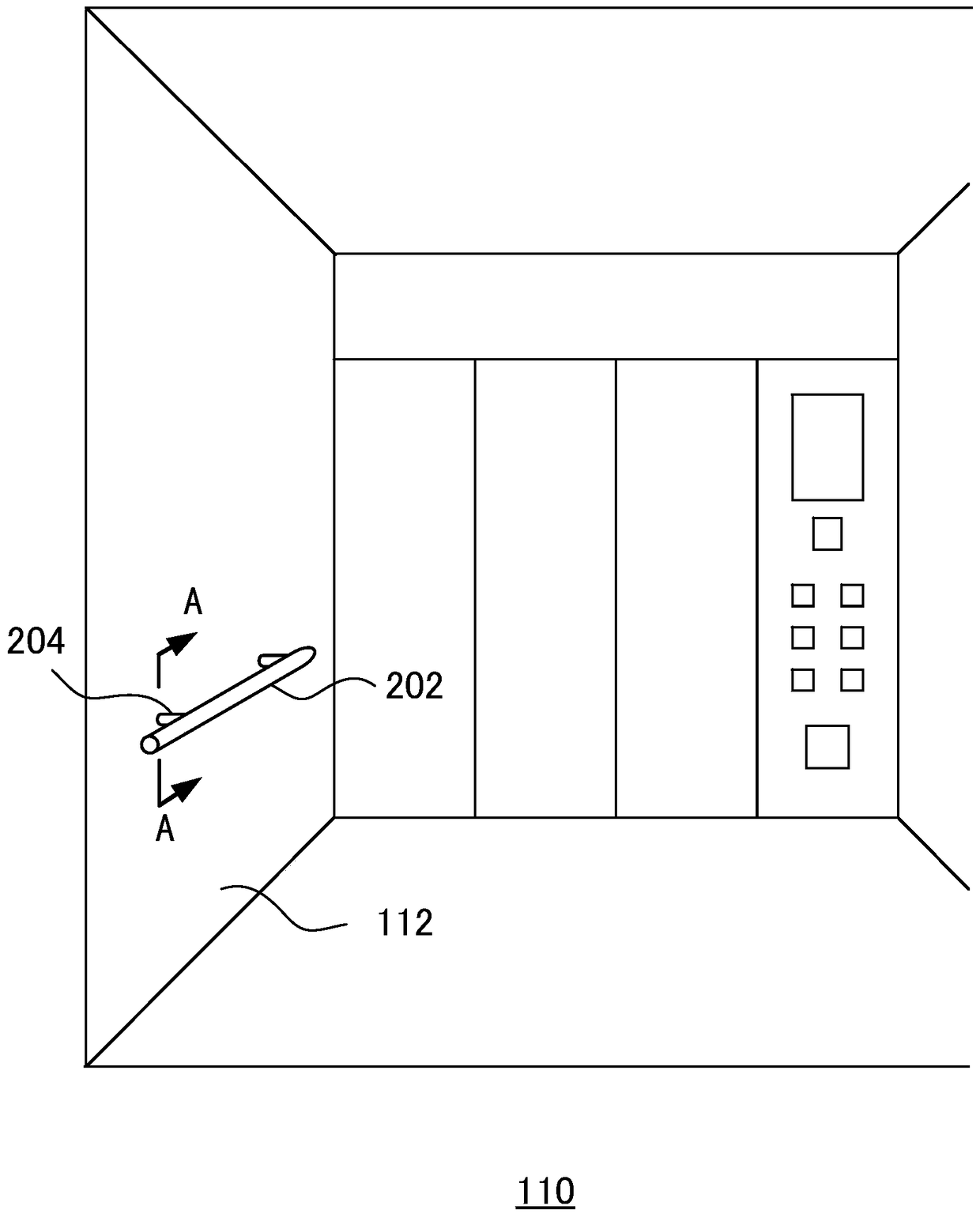
[0026] figure 2 It is a schematic perspective view schematically showing the interior of the car of the first embodiment of the elevator according to the present invention. A handrail 202 is provided inside the car 110 . The handrail 202 is connected with the car wall 112 through a bracket. The bracket of this embodiment is composed of two support rods 204 .

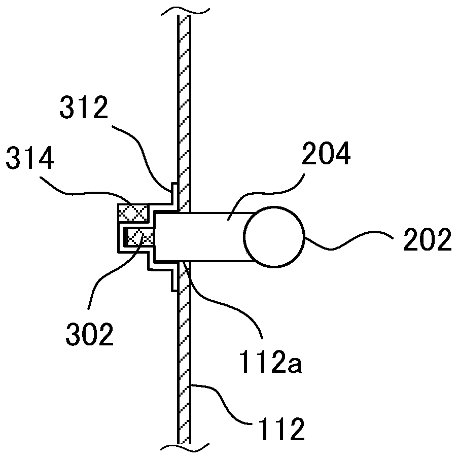
[0027] image 3 yes figure 2 Schematic representation of section A-A shown. As shown in the figure, a positioning block 302 is provided at the other end of the support rod 204 not connected to the armrest 202 . The positioning block 302 is made of a material that can be attracted by an electromagnet. For example, the positioning block 302 may be made of a magnet, or may be made of ferromagnetic materials such as iron alloy, nickel alloy or cobalt alloy. An installation frame 312 is provided on the outside of the car wall 112 , and the installation frame 312 can stably support the support rod 204 . One end of th...

no. 2 Embodiment >

[0033] Figure 7It is a schematic perspective view schematically showing the interior of the car of the second embodiment of the elevator of the present invention. This embodiment is a modified example of the first embodiment. In the present embodiment, the same symbols are attached to those components that are the same as, corresponding to, or equivalent to those of the first embodiment, and descriptions of these components will be omitted or simplified. The biggest difference between this embodiment and the first embodiment is that the bracket connecting the handrail 202 and the car wall 112 is composed of a support rod 204 and an armrest seat 206 . Since the armrest seat 206 connects the two support rods 204 into one body, the stability of the whole bracket is increased.

[0034] Figure 8 yes Figure 7 Schematic representation of the B-B section shown. As shown in the figure, a positioning block 302 is provided at the other end of the armrest seat 206 that is not conn...

no. 3 Embodiment >

[0040] Figure 11 It is a schematic perspective view schematically showing the interior of the car of the third embodiment of the elevator of the present invention. A handrail 202 is provided inside the car 110 . The handrail 202 is connected with the car wall 112 through a bracket. The bracket of this embodiment is composed of a support rod 204 and an armrest seat 206 .

[0041] Figure 12 yes Figure 11 Schematic representation of the C-C section shown. As shown in the figure, at the other end of the armrest seat 206 that is not connected to the support rod 204 and the armrest 202, more than two inserting rods 922 are provided. An installation frame 912 is provided on the outside of the car wall 112 , and the installation frame 912 can stably support the armrest seat 206 passing through the car wall 112 . One end of the armrest seat 206 provided with the insertion rod 922 is inserted into the car wall opening 112a provided on the car wall 112 from the inside of the car...


PUM


Abstract

The invention relates to an elevator. The elevator comprises a shaftway, an elevator car, a handrail, a ladder stand, a support, a positioning block and electromagnets, wherein the handrail is located in the elevator car; the ladder stand is arranged below a landing door sill of an end station on the bottom layer; the support is connected with the handrail and the car wall; the positioning block is arranged at the end, not connected with the handrail, of the support and made of a material capable of being attracted by the electromagnets; one electromagnet is arranged on the outer side of the car wall and can attract the positioning block to fix the support and the handrail to the car wall when powered on; and the other electromagnet is adjacent to a sill groove of the landing door sill of the end station at the bottom layer. A connecting body of the handrail, the support and the positioning block can be detached from the car wall by powering off the electromagnet located on the outer side of the car wall. The positioning block of the connecting body is inserted into the sill groove of the end station on the bottom layer, the electromagnet adjacent to the sill groove is powered on, the positioning block is attracted by the electromagnet adjacent to the sill groove to fix the connecting body to the landing door sill, and then the handrail can be used as an auxiliary handle for people to climb downwards or upwards a pit through the ladder stand.

Description

technical field [0001] The invention relates to an elevator, in particular to a handrail in an elevator car and a ladder for a bottom pit. Background technique [0002] The bottom part of the elevator shaft below the bottom end station is the pit. There are devices such as buffers in the bottom pit, and there are also ladders for maintenance personnel to go down to the bottom pit. The ladder is usually located below the landing sill of the bottom terminal station. Since the ladder is below the sill of the landing door, it is also difficult for people to directly see the ladder after opening the landing door. Therefore, maintenance personnel want to stand down from the bottom end to the pit, they need to put one foot down the pit first, find the ladder under the sill of the landing door, and then use the ladder to go down the pit. In the absence of handrails, maintenance personnel have to use their hands to pick up the opened landing door or the sill groove of the landing ...

Claims


Application Information

Patent Timeline
Patent Type & Authority Patents(China)
IPC IPC(8): B66B11/02B66B13/24
Inventor 富樫香介西山和义
Owner HITACHI BUILDING SYST CO LTD
Why Eureka
Try Eureka