A non-contact limit device for hanging sliding doors and its application method

A non-contact, limit device technology, applied to the suspension device of the wing leaf, window/door, door/window accessories, etc., can solve the problems of easy to mix passers-by, dust accumulation, etc., and achieve the effect of preventing shaking

Active Publication Date: 2017-12-08
SHENZHEN LOTUT INNOVATION DESIGN CO LTD
View PDF4 Cites 0 Cited by
  • Summary
  • Abstract
  • Description
  • Claims
  • Application Information

AI Technical Summary

Problems solved by technology

In order to prevent the swinging of the hanging sliding door, a limiter protruding from the ground will always be installed under the hanging sliding door, or a limiter embedded in a chute on the hanging sliding door will be used to limit the position. The former is easy to mix passers-by, and the latter It is easy to accumulate dust in the chute; at present, there is no anti-shake device for hanging sliding doors that does not have grooves, does not accumulate dust, and does not have protrusions to hinder walking.

Method used


Image

  • A non-contact limit device for hanging sliding doors and its application method
  • A non-contact limit device for hanging sliding doors and its application method
  • A non-contact limit device for hanging sliding doors and its application method

Examples


Embodiment Construction

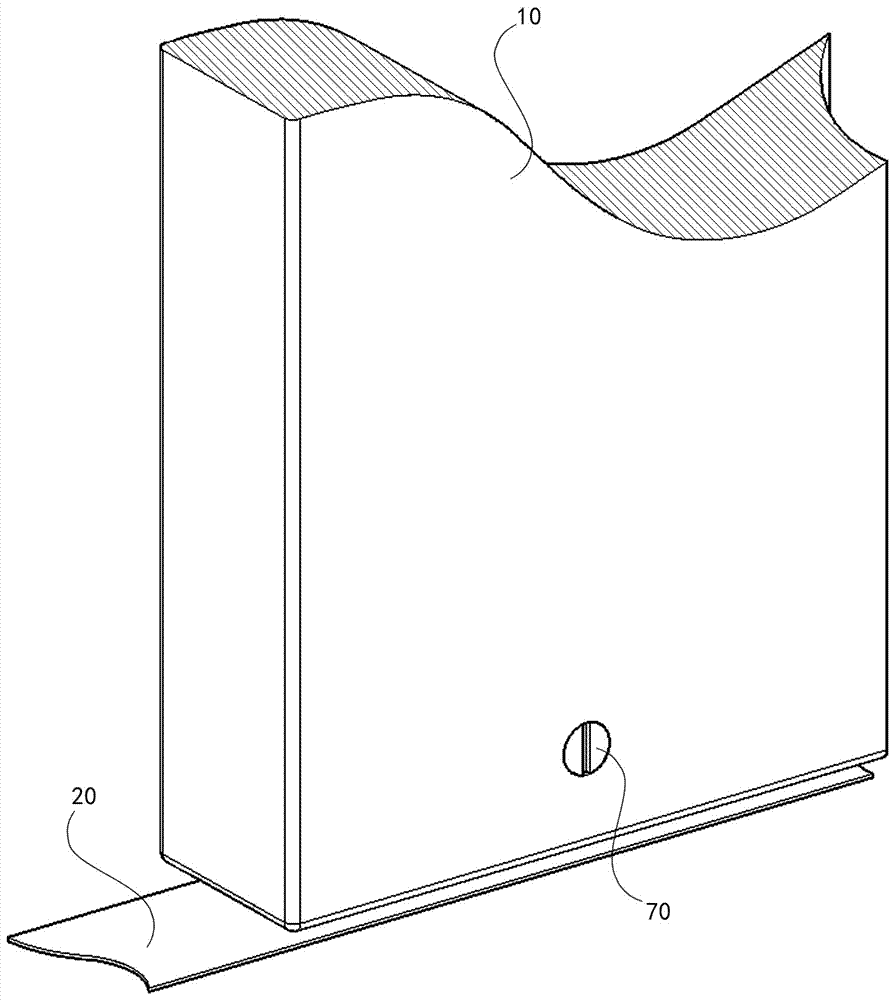
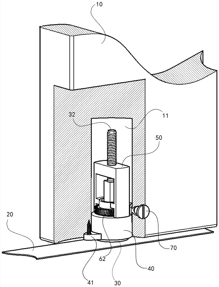
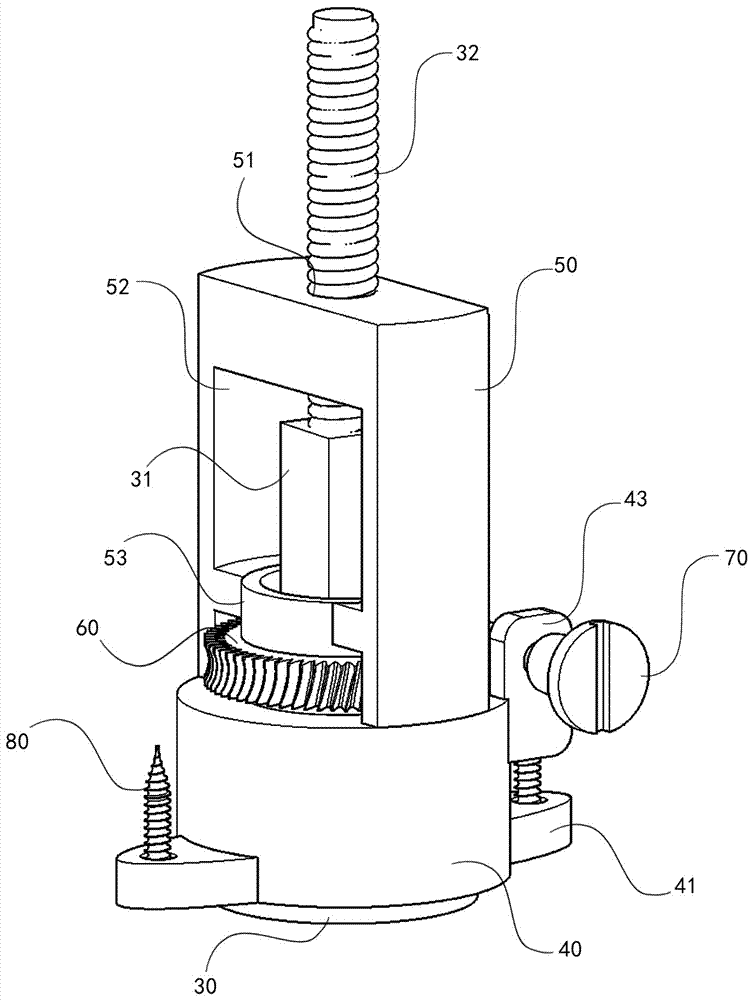
[0031] Below, the present invention will be further described in conjunction with accompanying drawing and embodiment: Figure 1 to Figure 5 As shown, a non-contact limit device for a hanging sliding door, including a hanging sliding door 10, a magnetophilic metal strip 20, a strong magnetic steel 30, a square shaft 31, a large threaded rod 32, a base 40, a bracket 50, and a gear 60 , square hole 61, twill tooth 62, adjusting bolt 70, self-tapping screw 80; It is characterized in that, the bottom of described hanging sliding door 10 has cavity 11, and base 40 and support 50 are placed in cavity 11; The magnetophilic metal strip 20 is installed below the hanging sliding door 10, parallel to the hanging rail above the hanging sliding door 10; a square shaft 31 is arranged above the strong magnetic steel 30, and a large threaded rod 31 is arranged above the square shaft 31 The two sides of the base 40 are provided with a positioning piece 41, and the positioning piece 41 is provi...


PUM


Abstract

The invention discloses a contactless limiting device of a hanging sliding door. The contactless limiting device comprises the hanging sliding door, an amphiphilic magnetic metal strip, strong magnet steel, a square shaft, a large threaded rod, a base, a bracket, a gear, a square hole, diagonal teeth, an adjusting bolt and a self-tapping screw. The contactless limiting device is characterized in that a hollow cavity is dug at the lower part of the hanging sliding door; the base and the bracket are arranged in the hollow cavity; the amphiphilic magnetic metal strip is arranged at the lower part of the hanging sliding door and is parallel to a hanger rail at the upper part of the hanging sliding door; the square shaft is arranged at the upper part of the strong magnet steel; the large threaded rod is arranged at the upper part of the square shaft; locating plates are arranged at two sides of the base; locating holes are formed in the locating plates; a first support sheet and a second support sheet are arranged at one side of the base; a front hole is formed in the first support sheet; a rear hole is formed in the second support sheet; a lower limiting ring is arranged on the base; an inner cavity of the base is arranged in the base; the bracket is fixed on the base; an inner threaded hole is formed in the bracket; an upper limiting ring is arranged in the inner cavity of the bracket; and the gear is arranged between the upper limiting ring and the lower limiting ring.

Description

technical field [0001] The invention relates to building decoration hardware, in particular to a non-contact limiting device for a hanging sliding door. Background technique [0002] In the independent, divisible and combined design of large space, the method of adding hanging sliding doors is often used. In order to prevent the swinging of the hanging sliding door, a limiter protruding from the ground will always be installed under the hanging sliding door, or a limiter embedded in a chute on the hanging sliding door will be used to limit the position. The former is easy to mix passers-by, and the latter It is easy to accumulate dust in the chute; at present, there is no anti-shaking device for the hanging sliding door that does not have a groove and does not accumulate dust, and does not have protrusions to hinder walking. Contents of the invention [0003] Aiming at the deficiencies in the prior art, the present invention provides a non-contact limiting device for hang...

Claims


Application Information

Patent Timeline
Patent Type & Authority Patents(China)
IPC IPC(8): E05F7/00E05D15/06E06B3/46
CPCE05D15/0626E05D2015/0695E05F7/00E06B3/4636
Inventor 王婧
Owner SHENZHEN LOTUT INNOVATION DESIGN CO LTD
Why Eureka
Try Eureka