A monitoring system and monitoring method for oil soil seepage in light oil depot area

A monitoring system and oil depot area technology, applied in the field of oil soil leakage monitoring system in light oil depot area, can solve the increased risk of leakage, unfavorable safety hazards, and the problem of leakage in light oil depot area can not be solved well and other issues to achieve the effect of improving accuracy and maintaining the safety of oil depots

Active Publication Date: 2019-04-26
中国人民解放军空军勤务学院
View PDF9 Cites 0 Cited by
  • Summary
  • Abstract
  • Description
  • Claims
  • Application Information

AI Technical Summary

Problems solved by technology

[0002] At present, there are perfect detection and emergency treatment mechanisms for a large number of leaks in light oil pipeline transportation, but the problem of leakage in light oil storage areas has not been well resolved
The main reason is that after the leakage occurs, if the leakage is not large, the traditional non-destructive detection and other methods cannot be used to determine whether the leakage occurs in time, lack of real-time performance, and are not conducive to eliminating potential safety hazards
[0003] Especially for strategic reasons, some oil depots have to be located in places with poor geological conditions, resulting in an increased risk of leakage, but there is a lack of effective leakage monitoring methods

Method used


Image

  • A monitoring system and monitoring method for oil soil seepage in light oil depot area
  • A monitoring system and monitoring method for oil soil seepage in light oil depot area

Examples


Embodiment Construction

[0028] In order to better explain the purpose and application method of the present invention, the present invention will be further described below in conjunction with the examples. The specific embodiments described here are only used to explain the present invention, not to limit the present invention.

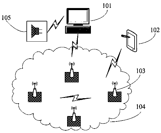
[0029] like figure 1 As shown, the present invention provides one embodiment. The system is generally composed of a central control computer 101 , a handheld terminal 102 , a soil leakage monitoring unit 103 and an alarm subsystem 105 . All the soil leakage monitoring units 103 form a wireless network 104 through the Zigbee protocol, and can be connected to the central control computer 101 through wired or wireless methods. When connecting through wireless methods, a wireless receiving device needs to be installed on the computer. The soil leakage monitoring unit 103 is buried in the soil below the oil pipeline in the reservoir area or in the soil around the oil tank, and...


PUM


Abstract

The invention discloses an oil soil leakage monitoring system of a light oil reservoir area. The system comprises a central control computer and a plurality of soil leakage monitoring units. A plurality of the soil leakage monitoring units is buried in the soil below the reservoir area oil conveying pipeline or the soil around oil tanks. The central control computer is used for receiving the state information monitored by a plurality of the soil leakage monitoring units through the wire or wireless mode, displaying the leakage monitoring state of the whole reservoir area on a display screen in the central control computer after processing the received information through a central processing unit in the central control computer, and transmitting the state information to each soil monitoring unit. The oil soil leakage monitoring system is capable of monitoring the underground pipeline leakage situation of the light oil reservoir area in real time, and overcoming the problem of the traditional non-destructive detection method that the leakage point cannot be determined in time, and is good for maintaining the safety of the oil reservoir. Especially, the system is arranged in the site with the bad geological conditions, the monitoring units are mainly arranged in the position with the high risk level through the estimation of the risk level, so the monitoring accuracy can be improved.

Description

technical field [0001] The invention relates to a monitoring system for oil soil seepage in a light oil depot area, belonging to the field of soil pollution monitoring. Background technique [0002] At present, there are perfect detection and emergency treatment mechanisms for a large number of leaks in light oil pipeline transportation, but the problem of leakage in light oil storage areas has not been well resolved. The main reason is that after the leakage occurs, if the amount of leakage is not large, the traditional non-destructive detection and other methods cannot be used to determine whether the leakage occurs in time, lack of real-time performance, and are not conducive to eliminating potential safety hazards. [0003] Especially for strategic reasons, some oil depots have to be located in places with poor geological conditions, resulting in an increased risk of leakage, but there is a lack of effective leakage monitoring methods. Contents of the invention [000...

Claims


Application Information

Patent Timeline
Patent Type & Authority Patents(China)
IPC IPC(8): F17D5/02
CPCF17D5/02
Inventor 陈利安孟凡芹朱江耿光辉贾丽曹泽煜
Owner 中国人民解放军空军勤务学院
Why Eureka
Try Eureka