Self-locking mechanism and electric device

A self-locking and knob technology, applied in mechanical equipment, control components, devices that prevent/restrict/restore the movement of parts of the control mechanism, etc. And other issues

Inactive Publication Date: 2017-06-13
BOE TECH GRP CO LTD +1
View PDF6 Cites 7 Cited by
  • Summary
  • Abstract
  • Description
  • Claims
  • Application Information

AI Technical Summary

Problems solved by technology

[0003] However, after the position adjustment of the existing gear mechanism is completed, if the knob 10 is bumped against the adjustment mechanism, the knob 10 will often reverse, causing the rack 40 to retreat, thereby affecting the user's use effect

Method used


Image

  • Self-locking mechanism and electric device
  • Self-locking mechanism and electric device
  • Self-locking mechanism and electric device

Examples


Embodiment Construction

[0029] The following will clearly and completely describe the technical solutions in the embodiments of the present invention with reference to the accompanying drawings in the embodiments of the present invention. Obviously, the described embodiments are only some, not all, embodiments of the present invention. Based on the embodiments of the present invention, all other embodiments obtained by persons of ordinary skill in the art without making creative efforts belong to the protection scope of the present invention.

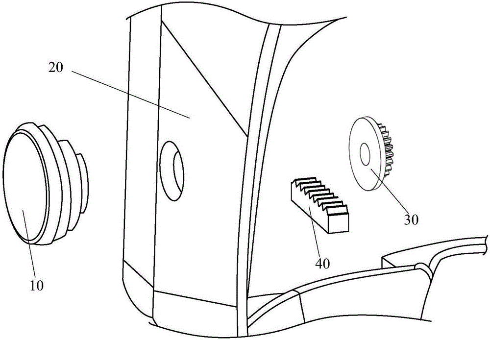
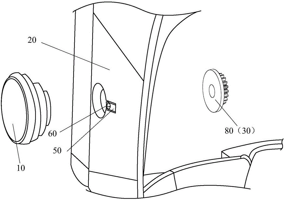
[0030] Embodiments of the present invention provide a self-locking mechanism, such as figure 2 , Figure 5 , Figure 7 as well as Figure 8 shown, including:

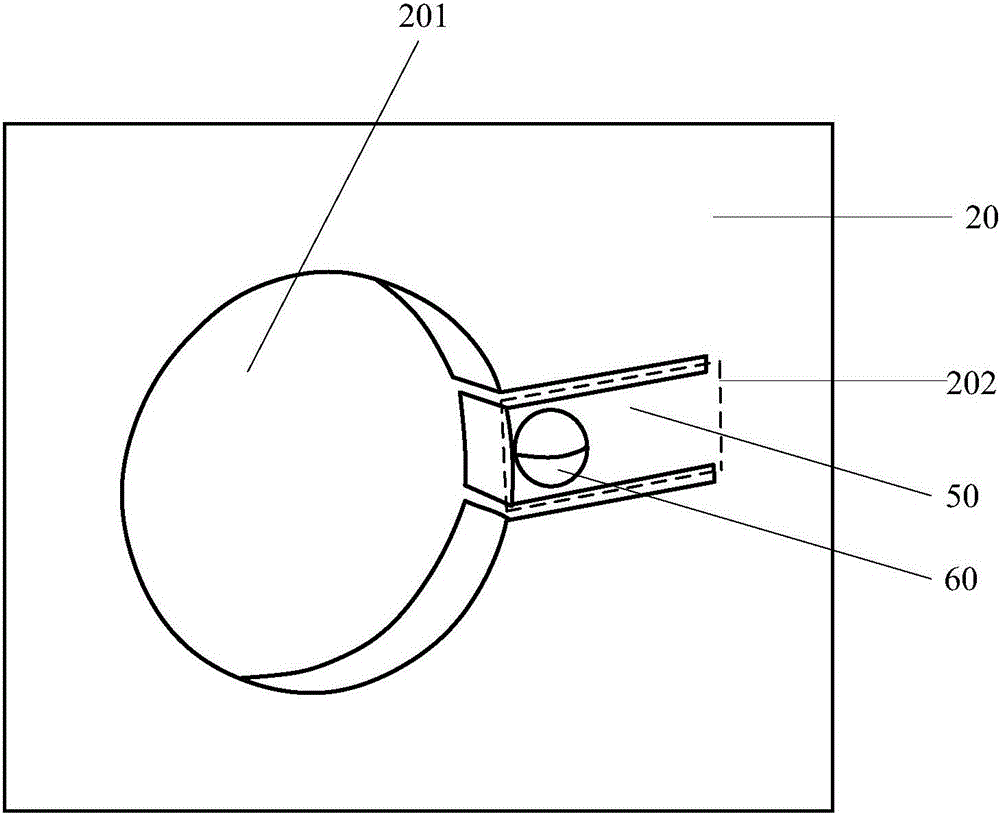
[0031] Housing 20, such as image 3 As shown, the housing 20 has a through hole 201 and an escape hole 202; the escape hole 202 is provided with an elastic member 50 connected to the wall of the avoidance hole 202, and the free end of the elastic member 50 can swing along the thickness direction of...


PUM


Abstract

The embodiment of the invention provides a self-locking mechanism and an electric device and relates to the technical field of self locking. By means of the self-locking mechanism, a rotary knob can be avoided from being reversed, and the travel of a driven member is prevented from receding. The self-locking mechanism comprises a shell provided with a through hole and a receding hole, the rotary knob and the driven member. An elastic element is arranged in the receding hole and connected with a hole wall of the receding hole, the free end of the elastic element can swing along the thickness direction of the shell, and a first clamping element is arranged on the elastic element; the rotary knob is arranged on the outer side of the shell, one end of the rotary knob penetrates through the through hole, a plurality of clamping elements are arranged on the side, close to the shell, of the rotary knob, and the distances of the second clamping elements to the center of rotation of the rotary knob are identical; the first clamping element can be clamped to or separated from the corresponding second clamping element under the deformation action of the elastic element; the driven element is arranged on the inner side of the shell, can be fixedly connected with the rotary knob and driven by the rotary knob to rotate. The self-locking mechanism is used for adjusting self locking of the structure.

Description

technical field [0001] The invention relates to the technical field of self-locking, in particular to a self-locking mechanism and electronic equipment. Background technique [0002] Most products in the prior art have adjustment mechanisms for adjusting distance or position. For example, a VR (Virtual Reality, virtual reality) helmet product is provided with an eye distance or an object distance adjustment mechanism, which is used to adjust the distance of the objective lens or the eyepiece. At present, the eye distance or object distance adjustment mechanism in VR helmet products uses a gear adjustment mechanism. Such as figure 1 As shown, the knob 10 is arranged on the outside of the housing 20, and the gear 30 is arranged on the inside of the housing 20. The knob 10 is fixedly connected to the gear 30 through the through hole on the housing 20. The gear 30 meshes with the rack 40, and the rotation of the knob 10 will Drive the gear 30 to rotate, and the rotation of th...

Claims


Application Information

Patent Timeline
Patent Type & Authority Applications(China)
IPC IPC(8): G02B27/01
CPCG02B27/0176G02B2027/0154G05G5/18G05G2505/00G05G1/08G05G5/12F16H19/04F16H2035/005F16H35/00
Inventor 田文红马占山孙志宇陈东张浩陈丽莉
Owner BOE TECH GRP CO LTD
Why Eureka
Try Eureka