Power control cabinet achieving safe power supply

A power control cabinet and safety technology, applied in the field of electric power, can solve problems such as troublesome operation, hidden dangers of operation, complicated wiring, etc., and achieve the effect of simple structure and improved stability

Inactive Publication Date: 2017-06-13
广州迅速光电科技有限公司
View PDF4 Cites 20 Cited by
  • Summary
  • Abstract
  • Description
  • Claims
  • Application Information

AI Technical Summary

Problems solved by technology

In the prior art, some manual power-off methods are often used, which often cause troublesome operation and cause hidden dangers in operation
When the drawer is pulled out, the wiring inside the cabinet is still connected. Because the electrical wiring occupies the walking path space of the cabinet cover, the wiring is complicated, and the contacts are easily exposed and easily accessible by the operator, which is not conducive to personal and equipment. Safety

Method used


Image

  • Power control cabinet achieving safe power supply
  • Power control cabinet achieving safe power supply
  • Power control cabinet achieving safe power supply

Examples


Embodiment Construction

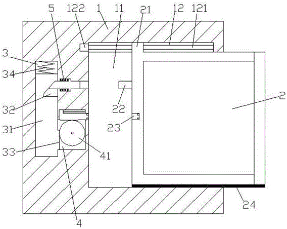
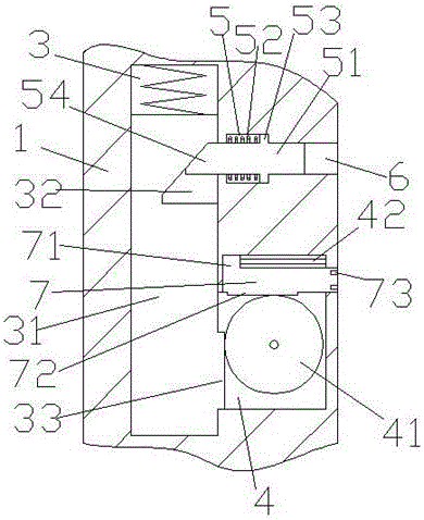
[0018] Such as Figure 1-3 As shown, a power control cabinet for safe power supply of the present invention includes a cabinet body 1 with an accommodating cavity 11 inside and a drawer 2 arranged in the accommodating cavity 11, and the left end of the drawer 2 is provided with a The insertion rod 22 extending on the left side and the power supply connection hole 23 arranged below the insertion rod 22, the cabinet body 1 opposite to the insertion rod 22 is provided with a through hole 6, and the through hole 6 The cabinet body 1 below is provided with a first transmission cavity 4, and the cabinet body 1 on the left side of the through hole 6 and the first transmission cavity 4 is provided with a second transmission cavity 3. The second transmission cavity 3 is provided with a transmission slider 31 that is slidably connected. The top of the transmission slider 31 is provided with a first spring 34. The right end of the transmission slider 31 is provided with an inclined chute...


PUM


Abstract

The invention discloses a power control cabinet achieving safe power supply. The power control cabinet comprises a cabinet body which is internally provided with a containing cavity and a drawer part arranged inside the containing cavity, the left end face of the drawer part is provided with an insertion and connection rod and a power supply connection hole formed in the lower portion of the insertion and connection rod, a through hole is formed in the portion, opposite to the insertion and connecting rod, inside the cabinet body, a first transmission cavity is formed in the portion, below the through hole, inside the cabinet body, a second transmission cavity is formed in the portion, at the left side of the through hole and the first transmission cavity, inside the cabinet body, the second transmission cavity is internally provided with a transmission sliding block, a first spring is arranged on the top of the transmission sliding block, an inclined sliding groove is formed in the right end face of the transmission sliding block, a first rack is arranged on the portion, below the inclined sliding groove, of the transmission sliding block, the first transmission cavity is internally provided with an external gear plate which is connected with the first rack in a meshed mode, a guide sliding rod is arranged on the upper portion of the external gear plate, a sliding block is arranged on the guide sliding rod, and a power supply insertion and connection rod is connected to the bottom of the sliding block. By means of the power control cabinet achieving safe power supply, the safety of maintenance is improved.

Description

technical field [0001] The invention relates to the technical field of electric power, in particular to a power control cabinet for safe power supply. Background technique [0002] The power control cabinet is a common component in the field of power switch control. The power control cabinet is used to install various switches, controllers and other power equipment for power control. In order to facilitate maintenance, the power control cabinet usually has drawers to push and pull to maintain the power equipment in it, and the cabinet body cover of the existing power control cabinet is often provided with some instruments and other devices, so that when the power control cabinet is working. Or display various power consumption parameters and operating signals. This is required to power these devices located on the cabinet lid. In order to ensure the safety of use and device maintenance, it is necessary to cut off the power for these cabinet covers when they are in the ope...

Claims


Application Information

Patent Timeline
Patent Type & Authority Applications(China)
IPC IPC(8): H02B1/36H02B11/127H01R13/629
CPCH02B1/36H01R13/629H02B11/127
Inventor 不公告发明人
Owner 广州迅速光电科技有限公司
Why Eureka
Try Eureka