Supercharge Your Innovation With Domain-Expert AI Agents!

Bandwidth estimating method, device and system

A bandwidth estimation and bandwidth technology, applied in the application field of communication technology, can solve problems such as low measurement accuracy, and achieve the effect of improving measurement accuracy and effectively measuring bandwidth

Active Publication Date: 2017-06-13
XIAN WANXIANG ELECTRONICS TECH CO LTD
View PDF5 Cites 0 Cited by
  • Summary
  • Abstract
  • Description
  • Claims
  • Application Information

AI Technical Summary

Problems solved by technology

[0023] Embodiments of the present invention provide a method, device and system for bandwidth estimation, to at least solve the technical problem of low measurement accuracy in the implementation process of the detection method provided by the related art

Method used


Image

  • Bandwidth estimating method, device and system
  • Bandwidth estimating method, device and system
  • Bandwidth estimating method, device and system

Examples


Embodiment 1

[0051] According to an embodiment of the present invention, an embodiment of a method for bandwidth estimation is provided. It should be noted that the steps shown in the flowcharts of the accompanying drawings can be executed in a computer system such as a set of computer-executable instructions, and, although A logical order is shown in the flowcharts, but in some cases the steps shown or described may be performed in an order different from that shown or described herein.

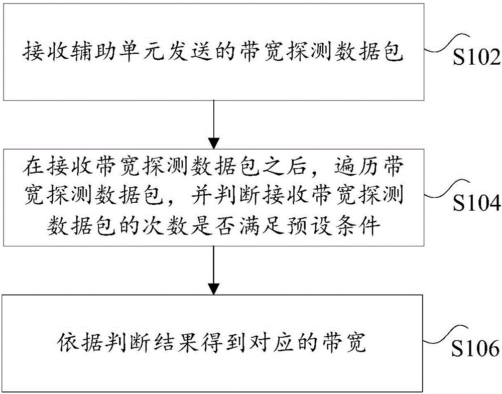
[0052] figure 1 is a schematic flowchart of a method for bandwidth estimation according to an embodiment of the present invention, such as figure 1 As shown, the method includes the following steps:

[0053] Step S102, receiving the bandwidth detection data packet sent by the auxiliary unit;

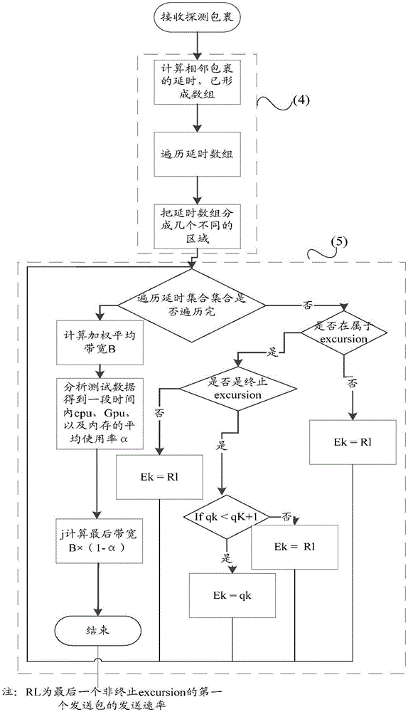
[0054] Step S104, after receiving the bandwidth detection data packet, traversing the bandwidth detection data packet, and judging whether the number of times of receiving the bandwidth detection data packet sati...

Embodiment 2

[0123] According to another aspect of the embodiments of the present invention, a device for bandwidth estimation is also provided, Figure 5 is a schematic structural diagram of a device for bandwidth estimation according to an embodiment of the present invention, such as Figure 5 shown, including:

[0124] The receiving module 52 is used to receive the bandwidth detection data packet sent by the auxiliary unit; the traversal module 54 is used to traverse the bandwidth detection data packet after receiving the bandwidth detection data packet, and judge whether the number of times of receiving the bandwidth detection data packet meets the preset condition ; The matching module 56 is used to obtain the corresponding bandwidth according to the judgment result.

[0125] In the device for bandwidth estimation provided in the embodiment of the present application, the bandwidth detection data packet sent by the auxiliary unit is received; after receiving the bandwidth detection d...

Embodiment 3

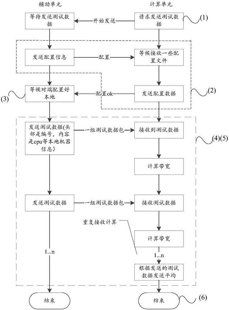
[0134] According to yet another aspect of the embodiments of the present invention, a bandwidth estimation system is also provided, such as figure 2 As shown, it includes: an auxiliary unit and a computing unit, the auxiliary unit is connected with the computing unit, wherein,

[0135] The auxiliary unit is used to determine the number of bandwidth detection data packets to be sent according to the current time, and sends the bandwidth detection data packets to the calculation unit; the calculation unit is used to receive the bandwidth detection data packets sent by the auxiliary unit to obtain the current bandwidth; wherein, the calculation Units include: Figure 5 A device for bandwidth estimation is shown.

[0136] The serial numbers of the above embodiments of the present invention are for description only, and do not represent the advantages and disadvantages of the embodiments.


PUM


Abstract

The invention discloses a bandwidth estimating method, device and system. The method comprises the following steps: receiving a bandwidth detection data packet transmitted by an auxiliary unit; traversing the bandwidth detection data packet after receiving the bandwidth detection data packet, and judging whether bandwidth detection data packet receiving times satisfy a preset condition or not; and acquiring a corresponding bandwidth according to a judgement result. Through adoption of the bandwidth estimating method, device and system, the technical problem of low measurement accuracy in an implementation process of a detection method in the prior art is solved.

Description

technical field [0001] The present invention relates to the application field of communication technology, in particular, to a bandwidth estimation method, device and system. Background technique [0002] In the video transmission, the smoothness of the transmitted image at the source end and the destination end is affected by many factors, such as the codec rate and the image transmission rate. The present invention is studying the factors affecting the image transmission rate in the network-existing network bandwidth- Under the premise of , an improvement to the existing bandwidth measurement algorithm pathchirp is proposed, so that it can provide a usable value for the sending rate of the video sent by the sender in video transmission, so that it can be transmitted as much as possible in video transmission The largest amount of data, so that the receiving end can process the video more smoothly, and the receiving end will not be in a state of starvation, so that the recei...

Claims


Application Information

Patent Timeline
Patent Type & Authority Applications(China)
IPC IPC(8): H04L12/24H04L12/873H04L12/911H04L47/52
CPCH04L41/0896H04L47/52H04L47/788
Inventor 钟炎培
Owner XIAN WANXIANG ELECTRONICS TECH CO LTD
Features
  • R&D
  • Intellectual Property
  • Life Sciences
  • Materials
  • Tech Scout
  • Unparalleled Data Quality
  • Higher Quality Content
  • 60% Fewer Hallucinations
Learn More