Method and device for generating routing information and determining transmission path

A transmission path and routing technology, applied in wireless communication, advanced technology, electrical components, etc., can solve problems such as low transmission efficiency and poor control of delay, and achieve the effect of controllable business requirements

Inactive Publication Date: 2017-06-13
CHINA ACAD OF TELECOMM TECH
View PDF4 Cites 14 Cited by
  • Summary
  • Abstract
  • Description
  • Claims
  • Application Information

AI Technical Summary

Problems solved by technology

[0004] The disadvantage of this method is: the transmissi

Method used


Image

  • Method and device for generating routing information and determining transmission path
  • Method and device for generating routing information and determining transmission path
  • Method and device for generating routing information and determining transmission path

Examples


Embodiment 1

[0118] This embodiment is used to illustrate the implementation of the control node management and control routing table.

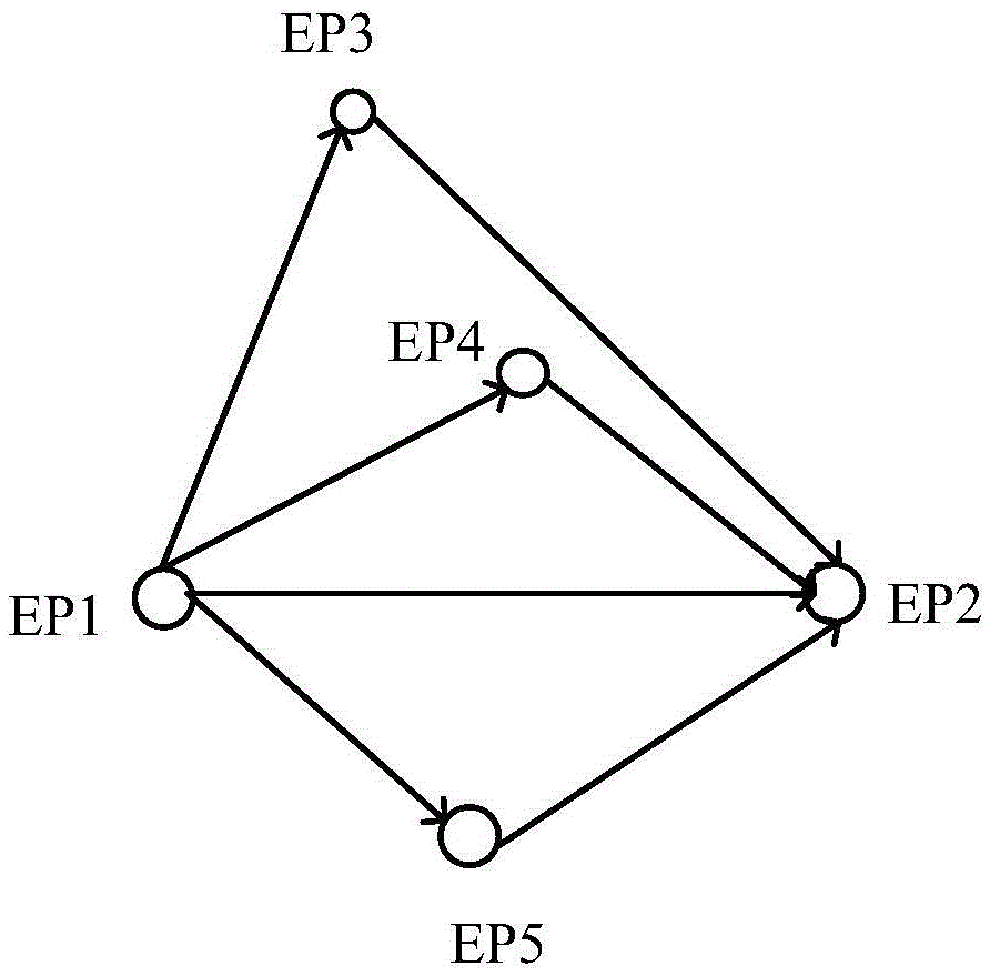
[0119] image 3 It is a schematic diagram of the routing environment of Embodiment 1. As shown in the figure, the transmission node pair is an end node 1 (sending node) and an end node 2 (receiving node), and intermediate end nodes (intermediate nodes) 3, 4, and 5 can be used for data Forward.

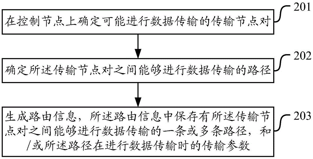
[0120] (1) The control node determines the transmission node pair (node ​​1, 2) and the intermediate node (node ​​3, 4, 5);

[0121] (2) According to the delay requirement, the control node determines that a maximum of two hops can be used, so all possible paths are as follows: image 3 As shown, the paths in the figure are indicated by connecting lines with arrows.

[0122] (3) The control node obtains the location information and channel status of nodes 1-5, and obtains channel fading information. Fading information is shown in Table 2.

[0123] Table 2:

...

Embodiment 2

[0167] This embodiment is used to illustrate the implementation of transmission path selection by the transmission node.

[0168] In order to better understand the cooperative implementation of the transmission node and the control node, this embodiment is carried out on the basis of the first embodiment, and it is assumed that the routing table between the transmission node pair 1 and 2 in Table 4 in the first embodiment is obtained.

[0169] Table 4:

[0170] path number transmission path capacity time delay 1 1->2 C12 T12 2 1->3->2 C1-3-2 T1-3-2

[0171] 3 1->4->2 C1-4-2 T1-4-2

[0172] Then you can choose the path as follows:

[0173] (1) The sending node extracts the storage path according to the order of the routing table. The routing table path between the transmitting node 1 and 2 is: path 1: 1->2, path 2: 1->3->2, path 2: 1- >4->2;

[0174] (2) The sending node selects the transmission path according to the restric...


PUM


Abstract

The invention discloses a method and device for generating routing information and determining transmission paths. The method comprises the following steps: determining transmission node pairs which may carry out data transmission on control nodes; determining the paths which can carry out data transmission between the transmission node pairs; generating the routing information, sending routing indicators to one or two transmission nodes and/or intermediate nodes in the transmission node pairs, wherein the routing indicators carry the routing information and the like; receiving the routing indicators on the transmission nodes and/or the intermediate nodes, and determining the paths for data transmission according to the routing indicators and/or the business requirements and the current transmission parameter. According to the method and device disclosed by the invention, the centralized routing management and distributed routing selection are combined, on the one hand, the transmission delay, reliability and other business requirements can be controllable, and on the other hand, the flexibility of the distributed system with multiple path scheme selection can be fully played.

Description

technical field [0001] The invention relates to the technical field of wireless communication, in particular to a method and a device for generating routing information and determining a transmission path. Background technique [0002] In the 5G system, in order to improve the end-to-end delay, a distributed network is introduced. The distributed network can avoid the core network delay of the traditional cellular network and minimize the delay on the network side. The end-to-end delay basically depends on the transmission delay of the air interface between the sending and receiving ends. [0003] The communication paths of the distributed network are diversified. Due to the existence of multi-hops, the path selection methods for the transmission between the end node pairs are diversified. How to achieve efficient routing is an important issue in distributed networks. A commonly used method is: the sending end node broadcasts data and target node information to the surroun...

Claims


Application Information

Patent Timeline
IPC IPC(8): H04W40/12H04W40/16H04W40/24
CPCH04W40/12H04W40/16H04W40/248Y02D30/70
Inventor 谌丽秦飞焦斌
Owner CHINA ACAD OF TELECOMM TECH
Why Eureka
Try Eureka