
Knapsack type electric fertilizer applicator

A knapsack and fertilizer applicator technology, applied in fertilization devices, fertilizer applicators with centrifugal wheels, applications, etc., can solve problems such as limited weight, high labor intensity, and impact on health, so as to reduce fatigue and improve work efficiency Effect

Inactive Publication Date: 2017-06-20
CHANGAN UNIV
View PDF9 Cites 8 Cited by
  • Summary
  • Abstract
  • Description
  • Claims
  • Application Information

AI Technical Summary

Problems solved by technology

The traditional agricultural fertilization method is that the fertilizers carry the bucket or bag containing fertilizer in one hand, and use the other hand to grasp the fertilizer while applying fertilizer. Due to the limited weight of the fertilizer at one time, farmers have to go back and forth multiple times to load the fertilizer and then fertilize.
On the other hand, in the process of fertilization, it is necessary to continuously complete repetitive actions such as grabbing fertilizer with hands, bending over, and spreading fertilizer. The hands directly touch the fertilizer, which affects the health of the body, and the efficiency is low. The labor intensity is high, time-consuming and labor-intensive. and uneven fertilization
Some of the existing knapsack fertilizers are fertilized by hand. Although the work efficiency has been improved, it still causes the fatigue of the arms of the fertilizers.

Method used


Image

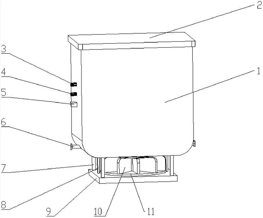
  • Knapsack type electric fertilizer applicator
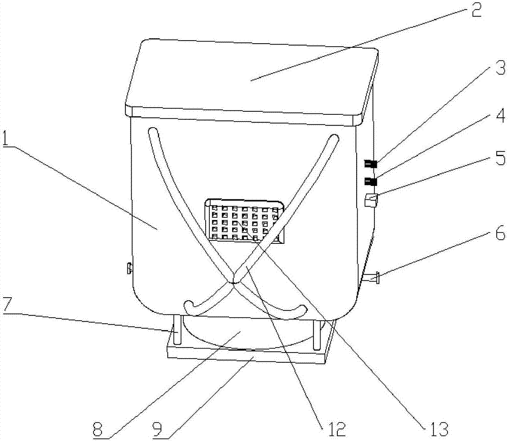
  • Knapsack type electric fertilizer applicator
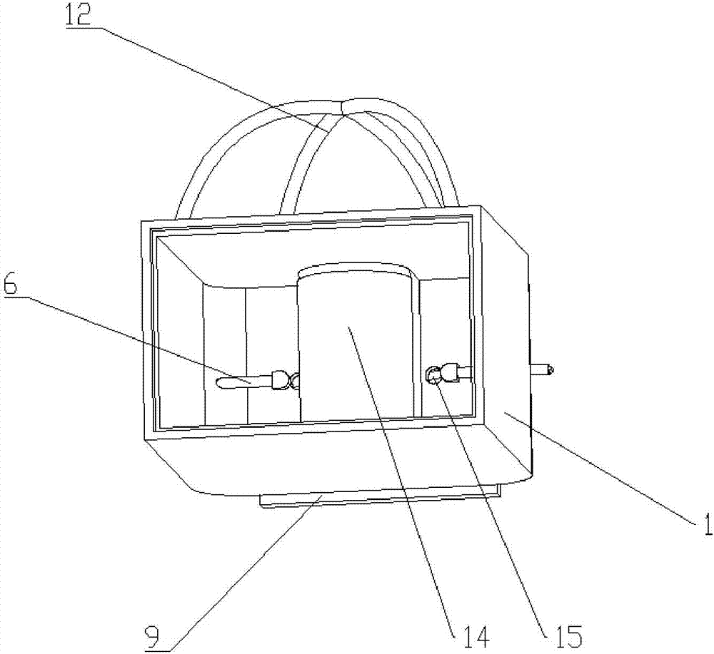
  • Knapsack type electric fertilizer applicator

Examples


Embodiment Construction

[0026] The present invention is described in further detail below in conjunction with accompanying drawing:

[0027] Such as Figure 1 to Figure 6 As shown, the knapsack electric fertilizer applicator includes a box body 1 and a back belt 12 arranged at the front end of the box body 1. The bottom of the box body 1 is provided with a discharge hole 15, and the side wall of the box body 1 is provided for controlling the size of the discharge hole 15. cock 6, the lower end of the box body 1 is provided with a spreading device and a power supply device; specifically, the spreading device includes an inner cover box 14-1 arranged at the inner lower end of the box body 1, and the upper end of the inner cover box 14-1 is provided with an inner cover Shell 14, the lower end of inner cover box 14-1 is provided with through hole 20 and fixing hole 21, and the motor 17 that is provided with fan blade disc 11 is fixed in the through hole of inner cover box 14-1, and the inner cover box 14...


PUM


Abstract

The invention discloses a knapsack type electric fertilizer applicator, which comprises a box body and slings, wherein the slings are arranged at the front end of the box body; the bottom of the box body is provided with discharge holes; the side wall of the box body is provided with plug cocks for controlling the sizes of the discharge holes; the lower end of the box body is provided with an inner cover case arranged at the lower end of the interior of the box body; the lower end of the inner cover case is provided with a through hole and fixing holes; a motor of which the lower end is provided with a fan blade wheel disk is fixedly arranged in the through hole of the inner cover case. Fertilizer slowly falls onto the fan blade wheel disk through the discharge holes; each fan blade wheel sheet uniformly separate the fertilizer falling from the discharge holes; the fertilizer falling onto the fan blade wheel disk is sprinkled forwards under the action of centrifugal force, and then is uniformly broadcasted through a broadcasting device; a fertilizer applying person only needs to adjust a self azimuth to be capable of adjusting a fertilizer sprinkling direction; in the whole fertilizer application process, the fertilizer applying person does not need to accomplish complicated motions of fertilizer grabbing, stooping, fertilizer sprinkling and the like, and only needs to forwards walk along the direction of crops; the fertilizer application working efficiency is greatly improved; the working fatigue problem of the fertilizer applying person is solved.

Description

technical field [0001] The invention belongs to the field of agricultural production tools, and in particular relates to a backpack electric fertilizer applicator. Background technique [0002] In today's agricultural production process, people fertilize rice or other crops to ensure the yield of crops. The traditional agricultural fertilization method is that the fertilizers carry the bucket or bag containing the fertilizer in one hand, and apply the fertilizer while grasping the fertilizer with the other hand. Because the weight of the fertilizer is limited at one time, the farmers have to go back and forth multiple times to load the fertilizer and then apply the fertilizer. On the other hand, in the process of fertilization, it is necessary to continuously complete repetitive actions such as grabbing fertilizer with hands, bending over, and spreading fertilizer. The hands directly touch the fertilizer, which affects the health of the body, and the efficiency is low. The l...

Claims


Application Information

Patent Timeline
IPC IPC(8): A01C17/00
CPCA01C17/001A01C17/008
Inventor 董袖青马军星杜振东史康宫朋飞吴彬李雄
Owner CHANGAN UNIV
Learn More