
Self-rotation grain distribution device

A grain distributing device and spin-type technology, applied in fruit hanging devices, botany equipment and methods, horticulture, etc., can solve the problems of small voids in grain piles, heat generation, and inability to effectively eliminate the accumulation of impurities, etc., to achieve uniform grain distribution Effect

Inactive Publication Date: 2017-06-20
胡妍
View PDF3 Cites 0 Cited by
  • Summary
  • Abstract
  • Description
  • Claims
  • Application Information

AI Technical Summary

Problems solved by technology

[0002] Modern grain logistics requires that grain enter and exit the warehouse quickly. The state has invested in the construction of large-scale modern grain warehouses, mainly shallow round warehouses and vertical silos. These two warehouse types have relatively small footprints, large storage capacity, and mechanized The advantages of high degree greatly speed up the speed of grain entering and leaving the warehouse; however, since the shallow round warehouse and the vertical silo have only one grain inlet at the top, and the grain inlet is tens of meters away from the ground, due to the physical properties of impurities and grain particles Different, it will cause serious automatic grading of grain and miscellaneous impurities, resulting in mineral impurities, especially the impurity cylinder area at the center of the circle, and light impurities floating to the surroundings to form a ring-shaped light impurity area, especially the impurity cylinder at the center of the circle. Due to a large amount of dusty and broken grains, the voids in grain piles are very small, which affects grain ventilation, cooling, precipitation, fumigation and insecticide, and a large number of microorganisms carried by impurities seriously affect the safe storage of grains.
This area is often hot, moldy, and agglomerated during grain storage, which seriously affects the safety of grain storage and increases the workload of grain storage
[0003] In order to reduce the accumulation of impurities caused by automatic grading caused by excessive concentration of grain from one grain inlet, certain measures are also taken at present, such as setting a conical hood under the grain inlet, so that the grain flowing into the grain inlet is along the slope of the conical hood. Move a certain distance outside to disperse the concentrated falling of the grain, but this method can only change the grain into a ring from a point, and there will still be an impurity ring area under the conical mask mouth, which cannot effectively eliminate the accumulation of impurities , due to the poor effect, it is rarely used at present, and has not been promoted so far

Method used


Image

  • Self-rotation grain distribution device
  • Self-rotation grain distribution device
  • Self-rotation grain distribution device

Examples


Embodiment 1

[0030] (Example 1, spin-type grain distributor)

[0031] In order to make the technical problems, technical solutions and advantages to be solved by the present invention clearer, the following will describe in detail with reference to the drawings and specific embodiments.

Embodiment 1)

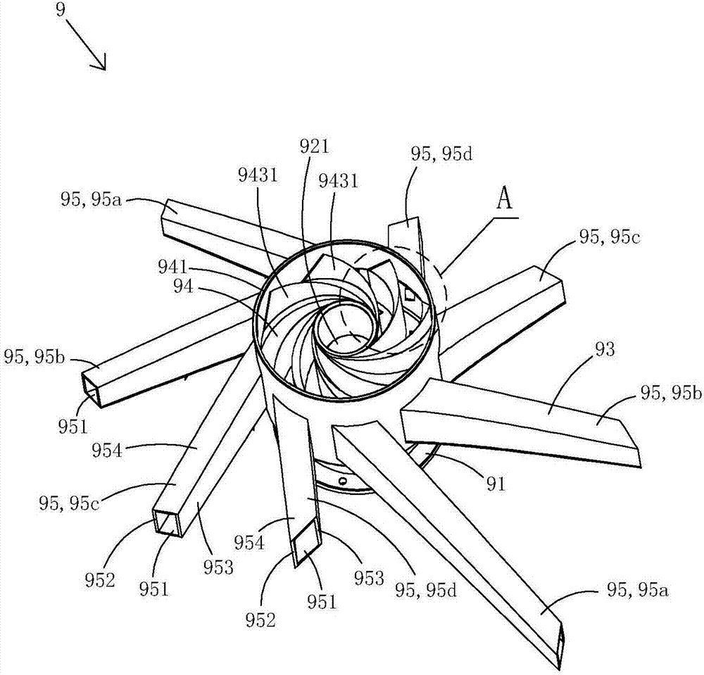
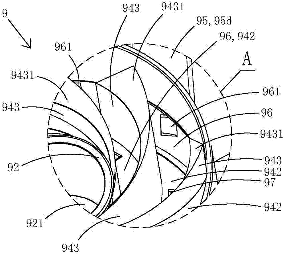
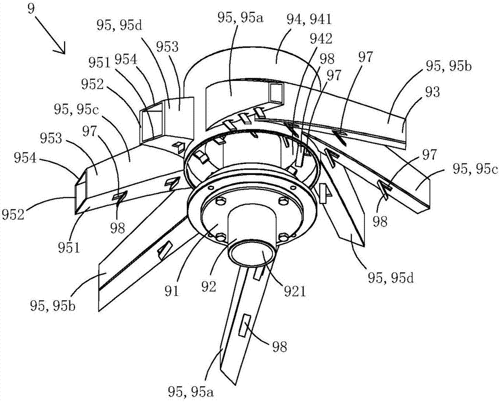
[0033] Figure 1 to Figure 6 One specific embodiment of the invention is shown. The invention provides a spin-type grain distributor, such as Figure 1 to Figure 6 As shown, the spin-type grain distributor 9 includes a bearing seat 91, a rotating shaft 92 rotatably arranged on the bearing seat, and a grain distribution piece 93 fixedly arranged on the rotating shaft; the rotating shaft is arranged along the vertical direction.

[0034] The cloth grain piece comprises a grain collection area 94 and eight grain slippers 95.

[0035] The grain collection area comprises an annular plate 941, a circular bottom wall 942 and eight involute plates 943, the rotating shaft is positioned at the center of the circular bottom wall, and the top of the rotating shaft is higher than the circular bottom wall. In this embodiment, the top of the rotating shaft level with the top of the ring plate.

[0036] The inner end of each involute plate is fixedly connected with the outer wall of the ro...

Embodiment 2

[0050] (Example 2, spin-type grain distributor)

[0051] This embodiment is basically the same as Embodiment 1, the difference is that: viewed from top to bottom, the second side plate in this embodiment is no longer a straight line, but an arc-shaped plate, and the arc-shaped plate is still vertically Line direction setting.


PUM


Abstract

The invention discloses a self-rotation grain distribution device comprising a bearing pedestal, a rotating shaft and a grain distribution piece, wherein the rotating shaft is arranged in the direction of a plumb line; the grain distribution piece comprises a grain collection area and a plurality of grain sliding barrels; the grain collection area comprises an annular plate, a round bottom wall, and a plurality of evolvent plates; the rotating shaft is positioned at the center of the round bottom wall; the two adjacent evolvent plates are combined in a clamping manner to form a flowing guiding channel; a plurality of grain outlets are formed in the annular plate; each grain outlet just faces a corresponding flowing guiding channel; each grain sliding barrel is fixedly arranged at the peripheral wall of the annular plate; each grain sliding barrel is communicated with one grain guiding channel by a corresponding grain outlet; each grain sliding barrel is arranged in an inclined manner in a direction from top to bottom; a self-rotation stress surface is arranged at the top end of each evolvent plate and is an inclined surface inclined downwards or an arc-shaped surface; and a grain falling opening is formed in the bottom wall of each flowing guiding channel. In the invention, the self-rotation performance can be realized, and the grain distribution is relatively uniform.

Description

technical field [0001] The invention belongs to the technical field of grain distribution equipment, and in particular relates to a spin-type grain distribution device. Background technique [0002] Modern grain logistics requires that grain enter and exit the warehouse quickly. The state has invested in the construction of large-scale modern grain warehouses, mainly shallow round warehouses and vertical silos. These two warehouse types have relatively small footprints, large storage capacity, and mechanized The advantages of high degree greatly speed up the speed of grain entering and leaving the warehouse; however, since the shallow round warehouse and the vertical silo have only one grain inlet at the top, and the grain inlet is tens of meters away from the ground, due to the physical properties of impurities and grain particles Different, it will cause serious automatic grading of grain and miscellaneous impurities, resulting in mineral impurities, especially the impurit...

Claims


Application Information

Patent Timeline
Patent Type & Authority Applications(China)
IPC IPC(8): A01F25/14A01F25/18
CPCA01F25/14A01F25/186
Inventor 胡妍
Owner 胡妍
Learn More