Gradient multi-cutter energy-efficient pulverizer

A high-efficiency, energy-saving, pulverizer technology, applied in the direction of mixers, mixers with rotating stirring devices, dissolution, etc., can solve the problems of single function, limited use, simple structure, etc., and achieve superior technical performance, exquisite design structure, Effects of Overcoming Design Hysteresis

Inactive Publication Date: 2017-06-20
LIUZHOU JINGYANG ENERGY SAVING TECH RES DEV
View PDF0 Cites 3 Cited by
  • Summary
  • Abstract
  • Description
  • Claims
  • Application Information

AI Technical Summary

Problems solved by technology

[0002] With the great development of urban and rural processing industry, planting and breeding industry, construction industry and the improvement of urban and rural people's life, beaters, mixers and soymilk machines for various purposes have emerged as the times require, but they all have lagging design, simple structure, single function, The use is not wide enough, and most of the beating and mixing technical equipment and the equipped electrical functions are used for their own purposes, that is, if they can be beaten, they can’t be stirred, or if they can be stirred, they can’t be beaten, etc. The disadvantages are lagging behind, which wastes production investment, materials, working hours, and space. , hydropower, etc., and cause low efficiency, mechanical wear and environmental protection and other comprehensive benefit problems

Method used


Image

  • Gradient multi-cutter energy-efficient pulverizer

Examples


example

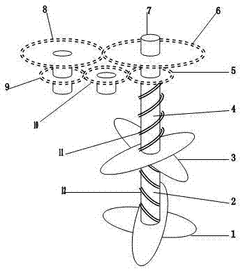
[0020] Connect the main drive shaft 7 of the step multi-knife high-efficiency energy-saving pulverizer of the present invention with an external related driver and start the main drive shaft 7, the main drive shaft 7 drives the main gear 6 and the main shaft rod 2 synchronously, and the main shaft rod 2 respectively drives the main stack The knife 1 and the main stirring front 12 work in the forward direction, and at the same time, the main gear 6 drives the auxiliary gear 8, and the auxiliary gear 8 drives the left gear 9, and the left gear 9 drives the middle left wheel 10, and the middle gear 10 drives the right gear 5. The right gear 5 drives the auxiliary shaft 4, and the auxiliary shaft 4 then drives the auxiliary stacking knife 3 and the auxiliary stirring front 11 to work in reverse. Due to the different diameters and indices of the gears, the positive and negative torques and speeds of the main gear 6 and the right gear are also different, and the main stacking cutter ...


PUM


Abstract

The invention relates to a gradient multi-cutter energy-efficient pulverizer. The gradient multi-cutter energy-efficient pulverizer is composed of a right gear, a main gear, a main drive shaft, an auxiliary gear, a left gear, a medium gear, main laminated cutters, a main shaft lever, auxiliary laminated cutters, an auxiliary shaft lever, auxiliary stirring edges and main stirring edges of a driving device and a stirring device. The bottom of the right gear is arranged at the upper end of the auxiliary shaft lever. The main gear is arranged on the middle section of a main rotating shaft. The main drive shaft is arranged inside the main gear, and the auxiliary laminated cutters are arranged at the lower end of the auxiliary shaft lever. The auxiliary gear is arranged at one side of the main gear. The left gear is arranged at the lower end of the auxiliary gear. The medium gear is arranged at one side of the right gear. The main laminated cutters are arranged at the bottom side of the lower end of the main shaft lever. The main shaft lever is arranged at the lower sides of the auxiliary laminated cutters. The auxiliary laminated cutters are arranged at the lower end of the auxiliary shaft lever. The auxiliary shaft lever is arranged at the lower side of the right gear. The auxiliary stirring edges are arranged on the outer side of the auxiliary shaft lever, and the main stirring edges are arranged on the outer side of the main shaft lever. The gradient multi-cutter energy-efficient pulverizer is exquisite in designed structure, superior in technical performance, multifunctional, high in practicality, capable of achieving synchronous and rapid stirring and further achieving energy saving and environmental protection, high in efficiency, low in manufacturing cost, safe, reliable and durable in use; and the application and popularization comprehensive cost performance is extremely high.

Description

technical field [0001] The invention relates to a pulverizer, in particular to a multi-knife high-efficiency and energy-saving pulverizer in stages. Background technique [0002] With the great development of urban and rural processing industry, planting and breeding industry, construction industry and the improvement of urban and rural people's life, beaters, mixers and soymilk machines for various purposes have emerged as the times require, but they all have lagging design, simple structure, single function, The use is not wide enough, and most of the beating and mixing technical equipment and the equipped electrical functions are used for their own purposes, that is, if they can be beaten, they can’t be stirred, or if they can be stirred, they can’t be beaten, etc. The disadvantages are lagging behind, which wastes production investment, materials, working hours, and space. , hydropower, etc., and cause low efficacy and comprehensive benefit problems such as mechanical we...

Claims


Application Information

Patent Timeline
Patent Type & Authority Applications(China)
IPC IPC(8): B02C18/08B02C18/24B02C18/18B01F7/16
CPCB02C18/08B02C18/18B02C18/24B01F27/84
Inventor 韦战
Owner LIUZHOU JINGYANG ENERGY SAVING TECH RES DEV
Why Eureka
Try Eureka