Supercharge Your Innovation With Domain-Expert AI Agents!

Steel bar bending machine with adjustable fixing plate

A technology for bending steel bars and fixing plates, which is applied in the field of steel bar bending machines, can solve the problems of inconvenient use of steel bar bending machines, and achieve the effect of convenient use

Inactive Publication Date: 2017-06-20
长葛市老城昌宝建筑机械配件厂
View PDF8 Cites 0 Cited by
  • Summary
  • Abstract
  • Description
  • Claims
  • Application Information

AI Technical Summary

Problems solved by technology

[0002] The steel bar bending machine has a working panel, on which there is a bending disc, on which there are grooves for placing dynamic bending parts, and on the working panel there is a fixed plate, on which there are grooves for placing static bending parts. In the prior art, the fixing plate is fixed on the working panel, and such a steel bar bending machine has the disadvantage of being inconvenient to use

Method used


Image

  • Steel bar bending machine with adjustable fixing plate
  • Steel bar bending machine with adjustable fixing plate

Examples


Embodiment Construction

[0010] The present invention will be further described below in conjunction with the drawings.

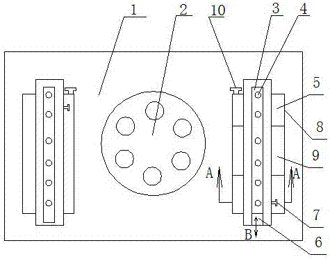
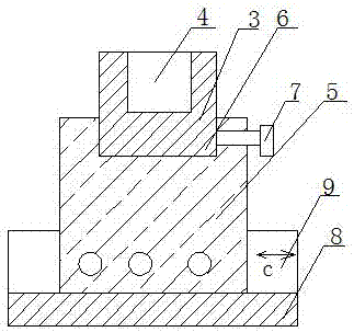
[0011] Such as figure 1 As shown, the steel bar bending machine with adjustable fixed plate includes a bending machine body. The bending machine body has a working panel 1, a bending plate 2 on the working panel, and a fixed plate 3 on the working panel. The groove 4 of the curved mixing piece is characterized in that there is a first sliding plate 5 under the fixed plate, and a first sliding groove 6 that moves longitudinally on the first sliding plate. The fixed plate slides in the first sliding groove in a direction such as As shown in the direction B in the figure, the bottom of the fixed plate has a structure installed in the first sliding groove, and on the side of the first sliding groove there is a first positioning pin 7 for positioning the fixed plate.

[0012] Furthermore, there is a second sliding plate 8 under the first sliding plate, and the second sliding plate also has a...


PUM


Abstract

The invention relates to building machines, in particular to a steel bar bending machine with an adjustable fixing plate. The steel bar bending machine comprises a bending machine body. The bending machine body is provided with a work panel. The work panel is provided with a bending disc. The workbench is further provided with the fixing plate. The fixing plate is provided with a groove containing a static bent stirring piece. The steel bar bending machine is characterized in that a first sliding plate is arranged below the fixing plate and provided with a first sliding groove longitudinally moving, and the fixing plate slides in the first sliding groove; a structure arranged in the first sliding groove is arranged below the fixing plate, a first positioning pin for positioning the fixing plate is arranged on the side face of the first sliding groove; a second sliding plate is further arranged below the first sliding plate and further provided with a transverse second sliding groove, and the second sliding plate slides in the second sliding groove; and a structure matched with the second sliding groove is arranged below the first sliding plate and arranged in the second sliding groove, and a second positioning pin for positioning the first sliding plate is further arranged on the side face of the second sliding groove. The steel bar bending machine has the beneficial effect of being convenient to use.

Description

Technical field [0001] The invention relates to construction machinery, in particular to a steel bar bending machine. Background technique [0002] The steel bar bending machine has a working panel, there is a bending plate on the working panel, a groove for placing dynamic bending parts on the bending plate, a fixed plate on the working panel, and a groove for placing static bending parts on the fixed plate. In the prior art, the fixing plate is fixed on the working panel, and such a steel bar bending machine has the disadvantage of inconvenience. Summary of the invention [0003] The purpose of the present invention is to provide an easy-to-use rebar bending machine with adjustable fixing plates in view of the above shortcomings. [0004] The technical solution of the present invention is realized as follows: a steel bar bending machine with adjustable fixed plate includes a bending machine body, the bending machine body has a working panel, a bending plate on the working panel, ...

Claims


Application Information

Patent Timeline
IPC IPC(8): B21F1/00
CPCB21F1/00
Inventor 耿彦昌
Owner 长葛市老城昌宝建筑机械配件厂
Features
  • R&D
  • Intellectual Property
  • Life Sciences
  • Materials
  • Tech Scout
  • Unparalleled Data Quality
  • Higher Quality Content
  • 60% Fewer Hallucinations
Learn More