Precise and automatic cutting device and method for Teflon pipe

A Teflon tube, automatic technology, applied in the direction of metal processing, etc., can solve the problems of poor control, poor incision quality, easy to cut into bevels, etc., to eliminate bending or flattening, good incision quality, and increase the length The effect of precision

Active Publication Date: 2017-06-20
南通正耀电气科技有限公司
View PDF5 Cites 14 Cited by
  • Summary
  • Abstract
  • Description
  • Claims
  • Application Information

AI Technical Summary

Problems solved by technology

Since the feeding is carried out by pressing the thin tube with the roller, the contact surface is small, and the pressure is adjusted manually, which is difficult to control. The thin tube is hard and easy to be bent or flattened, or slipped and deviated, and the cutting length and accuracy are difficult to guarantee. The quality of the cut is poor, it is easy to cut into oblique cuts, and the smaller the diameter of the thin tube, the more difficult it is to feed the material. This kind of material waste caused by bending or flattening the tube is huge

Method used


Image

  • Precise and automatic cutting device and method for Teflon pipe
  • Precise and automatic cutting device and method for Teflon pipe
  • Precise and automatic cutting device and method for Teflon pipe

Examples


Embodiment approach 1

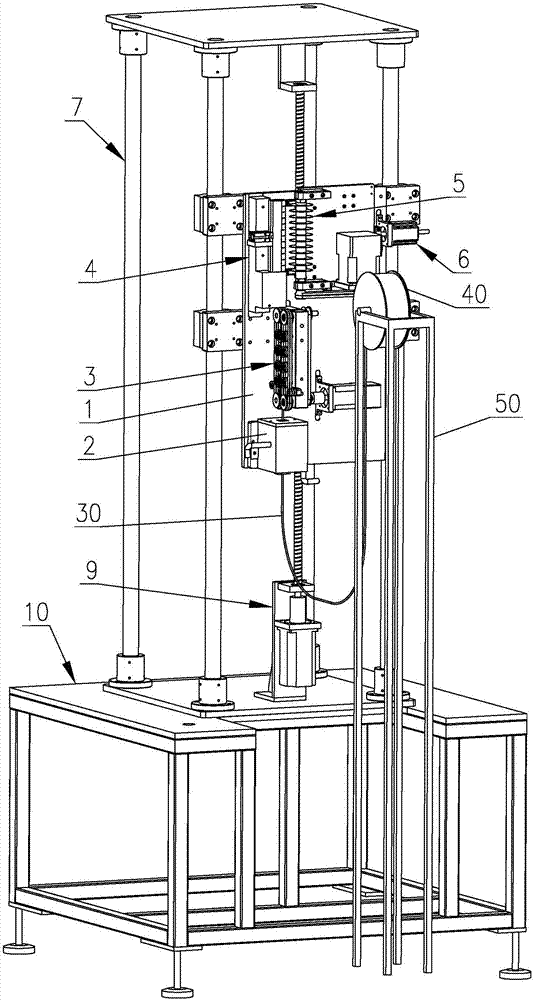
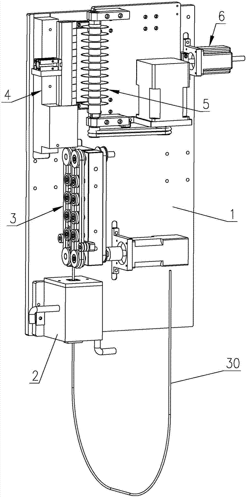
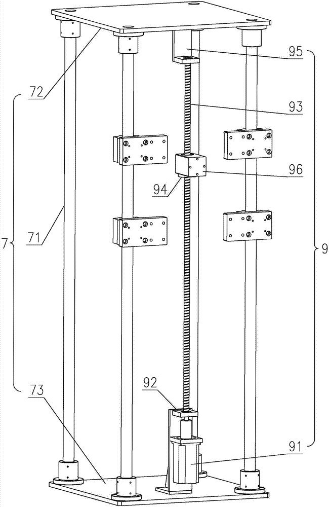
[0114] Such as figure 1 As shown, a Teflon tube precision automatic cutting equipment, which includes a base 1, a cooling water tank 2, a conveying mechanism 3, a clamping mechanism 4, a cutting mechanism 5, a cutting driving mechanism 6, a support frame 7, and a U-shaped tube length The compensation mechanism 9, the frame 10, and the support frame 7 are provided with at least two support columns 71; the cooling water tank 2, the conveying mechanism 3, the clamping mechanism 4, and the cutting drive mechanism 6 are installed on the base 1 respectively, and the cutting mechanism 5 is installed on the cutting On the driving mechanism 6, the support frame 7 is installed on the frame 10, the base 1 is slidably connected with the support column 71, the U-shaped tube length compensation mechanism 9 is installed in the support frame 7 and connected with the base 1; the U-shaped Teflon tube 30 passes through the cooling water tank 2 and is inserted into the conveying mechanism 3, and ...

Embodiment approach 2

[0122] Such as Figure 8 , Figure 9 As shown, the second embodiment is basically the same as the first embodiment, except that the clamping mechanism 4 is different. The clamping mechanism 4 of the second embodiment includes a main clamping block 44, and a plurality of secondary clamps are arranged on the front of the main clamping block 44 The holding block 45, the front of the main holding block 44 and the auxiliary holding block 45 are all provided with an arc-shaped groove 431 for clamping the Teflon tube 30, and the side of the main holding block 44 is provided with a breach 432 for cutting, The auxiliary clamping block 45 and the notch 432 are designed according to the length of the Teflon tube 30 after being cut, and a plurality of them can be evenly designed, and the second embodiment of the present invention is designed to be 12; the main clamping block 44 is installed by the main clamping block 46 is fixedly installed on the base 1.

[0123] The present invention ...


PUM


Abstract

The invention provides a precise and automatic cutting device for a Teflon pipe. The precise and automatic cutting device comprises a base, a cooling water tank, a conveying mechanism, a clamping mechanism, a cutting mechanism, a cutting driving mechanism, a support frame, a U-shaped pipe length compensation mechanism and a rack, wherein the U-shaped Teflon pipe penetrates through the cooling water tank to be inserted into the conveying mechanism; the Teflon pipe with a fixed length is conveyed into the clamping mechanism to be clamped by the conveying mechanism; the cutting driving mechanism drives the cutting mechanism to cut the Teflon pipe in the clamping mechanism; and the U-shaped pipe length compensation mechanism drives the base to move upwards or downwards to compensate the length of the Teflon pipe which is inserted into the cooling water tank. The invention further discloses a precise and automatic cutting method for the Teflon pipe. The precise and automatic cutting method comprises the following method of A, preparing; B, inserting; C, compensating; D, conveying for clamping and outputting; E, rotating; F, cutting and resetting; G releasing; H re-conveying, ejecting-out, re-outputting and re-clamping; and returning to the step F for cutting repeatedly. By adopting the precise and automatic cutting device and method, the length precision of the cut pipes can be effectively improved; and phenomena of pipe bending or flattening are reduced or even eradicated.

Description

technical field [0001] The invention relates to the technical field of industrial machinery automation, in particular to a precision automatic cutting equipment and method for Teflon tubes. Background technique [0002] In the cutting operation of Teflon thin tubes, it is usually necessary to cut a variety of short tubes of specific lengths for one type of tube. smooth. [0003] At present, for cutting Teflon thin tubes of a specific length, the common way is to use rollers to feed the material, and then cut it with a blade. The method is to press a Teflon thin tube with a pair of rollers. The active roller rotates to apply frictional force to the thin tube, and feeds the material forward continuously. After passing through a specific mold, when the thin tube reaches the predetermined length, the cutter completes the cutting action. Since the feeding is carried out by pressing the thin tube with the roller, the contact surface is small, and the pressure is adjusted manuall...

Claims


Application Information

Patent Timeline
IPC IPC(8): B26D1/157B26D7/06B26D7/02B26D5/08
CPCB26D1/157B26D5/08B26D7/02B26D7/0625B26D2007/013
Inventor 李鲜元
Owner 南通正耀电气科技有限公司
Why Eureka
Try Eureka