
Hardware processing equipment

A technology for processing equipment and hardware, which is applied in the field of hardware processing equipment, can solve problems such as prolonged construction time, low efficiency, and poor incision quality, and achieve the effects of improving quality, avoiding debris splashing, and ensuring cleanliness

Active Publication Date: 2020-09-29
宁波隆锐机械制造有限公司
View PDF5 Cites 0 Cited by
  • Summary
  • Abstract
  • Description
  • Claims
  • Application Information

AI Technical Summary

Problems solved by technology

However, the length of the pipe fittings is fixed when they leave the factory, and users need to cut the pipe fittings according to their needs
At present, the most common cutting tool is the grinding wheel saw. The cutting speed of the grinding wheel saw is very fast, and the operation is very simple and convenient, but its cutting accuracy is low, the sparks during cutting are large, and the quality of the cut is poor.
Therefore, if the user has high requirements for the accuracy of the length of the pipe fittings and the high quality of the cut, the pipe fittings need to be finished, such as grinding, allowance processing, etc., which leads to long cutting time of the entire pipe fittings, low efficiency, Extend construction time

Method used


Image

  • Hardware processing equipment
  • Hardware processing equipment
  • Hardware processing equipment

Examples


Embodiment Construction

[0018] The following is further described in detail through specific implementation methods:

[0019] The reference signs in the accompanying drawings of the specification include:

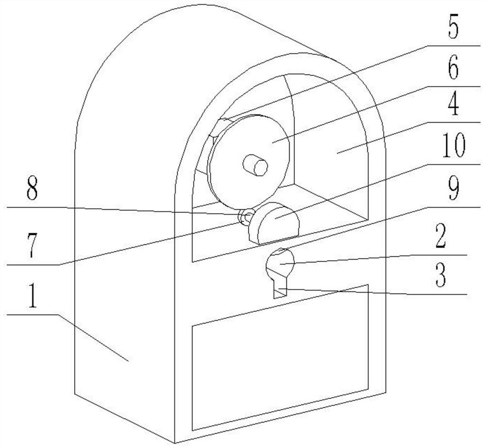
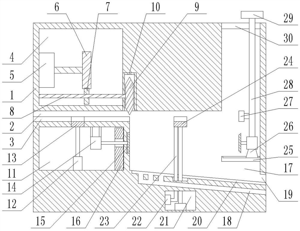
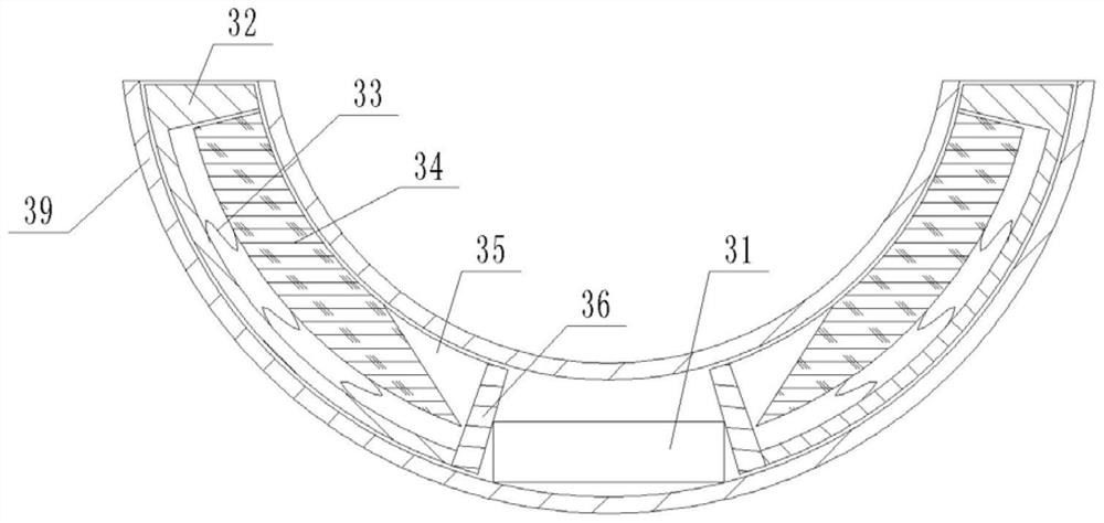
[0020] Frame 1, processing hole 2, rectangular groove 3, upper chamber 4, first motor 5, first gear 6, second gear 7, gear shaft 8, cutting tool 9, shroud 10, lower chamber 11, cylinder 12. The first fixed claw 13, the second motor 14, the grinding block 15, the second electromagnet 16, the grinding chamber 17, the slag outlet 18, the outlet 19, the outlet trough 20, the bottom cavity 21, the air pump 22, Air pipe 23, second fixed claw 24, fixed plate 25, sliding seat 26, block 27, connecting plate 28, handle 29, top groove 30, first electromagnet 31, arc bar 32, spring 33, pressing block 34 , placement groove 35, permanent magnet 36, air bag 37, elastic bar 38, first bottom plate 39, second bottom plate 40.

[0021] The embodiment is basically as attached figure 1 , figure 2 Shown:

[0022]...


PUM


Abstract

The invention belongs to the technical field of machining of hardware and particularly discloses hardware machining equipment. The hardware machining equipment comprises a base; the base is horizontally provided with a machining hole; the base is further internally provided with an upper chamber, a lower chamber and a grinding chamber; the machining hole is positioned between the upper chamber andthe lower chamber; a cutting knife is arranged inside the upper chamber; the lower part of the cutting knife extends to a position above the machining hole; the lower chamber and the grinding chamberare each internally provided with a lifting mechanism; the lifting mechanism inside the lower chamber is provided with first fixing claws which can be used for fixing a pipe part; the lifting mechanism inside the grinding chamber is provided with second fixing claws which can be used for fixing the pipe part; the first fixing claws and the second fixing claws both extend into the machining hole;the upper end of the grinding chamber communicates with the machining hole; the second fixing claws are positioned inside the grinding chamber; the two sides of the grinding chamber are each providedwith a circular platform-shaped grinding block; and each grinding block is provided with abrasive paper. The invention aims to provide the hardware machining equipment which can be used for implementing both cutting and grinding of the pipe part.

Description

technical field [0001] The invention belongs to the technical field of hardware processing, and specifically discloses hardware processing equipment. Background technique [0002] Pipe fittings are one of the most common hardware. Pipes can be divided into metal pipes and plastic pipes according to their materials. The length of pipes needs to be changed according to their use during use. For example, gas and liquid pipelines for production generally use metal pipes. And the length of pipeline is longer, and household pipeline adopts plastic pipeline mostly, and the length of pipeline is generally shorter. However, the length of the pipe fittings is fixed when they leave the factory, and users need to cut the pipe fittings according to their needs. At present, the most common cutting tool is a grinding wheel saw. The cutting speed of the grinding wheel saw is very fast, and the operation is also very simple and convenient, but its cutting accuracy is low, the sparks during ...

Claims


Application Information

Patent Timeline
Patent Type & Authority Patents(China)
IPC IPC(8): B23P23/04
CPCB23P23/04
Inventor 毛薇薇
Owner 宁波隆锐机械制造有限公司
Learn More