Angled wedge electronic lock and method of use thereof

An electronic lock and wedge-type technology, which is applied to building locks, non-mechanical transmission-operated locks, buildings, etc., can solve the problems of lock body length, inconvenient production, assembly, correction, tamper resistance and poor stability, etc., to achieve It is easy to assemble and use, good in tamper resistance and stability, and small in radial displacement and error.

Active Publication Date: 2019-06-25
宁波生久科技有限公司
View PDF5 Cites 0 Cited by
  • Summary
  • Abstract
  • Description
  • Claims
  • Application Information

AI Technical Summary

Problems solved by technology

[0003] In order to overcome the above-mentioned shortcomings, the purpose of the present invention is to provide a wedge-type electronic lock and its use method in the field, so that it can solve the problems of long latch body, fragility, and easy jamming caused by poor structural design of existing similar products. Prying resistance and poor stability, production, assembly, repair technical problems inconvenient

Method used


Image

  • Angled wedge electronic lock and method of use thereof
  • Angled wedge electronic lock and method of use thereof
  • Angled wedge electronic lock and method of use thereof

Examples


Embodiment Construction

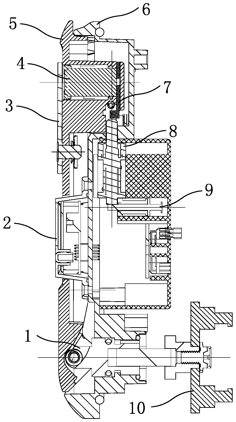
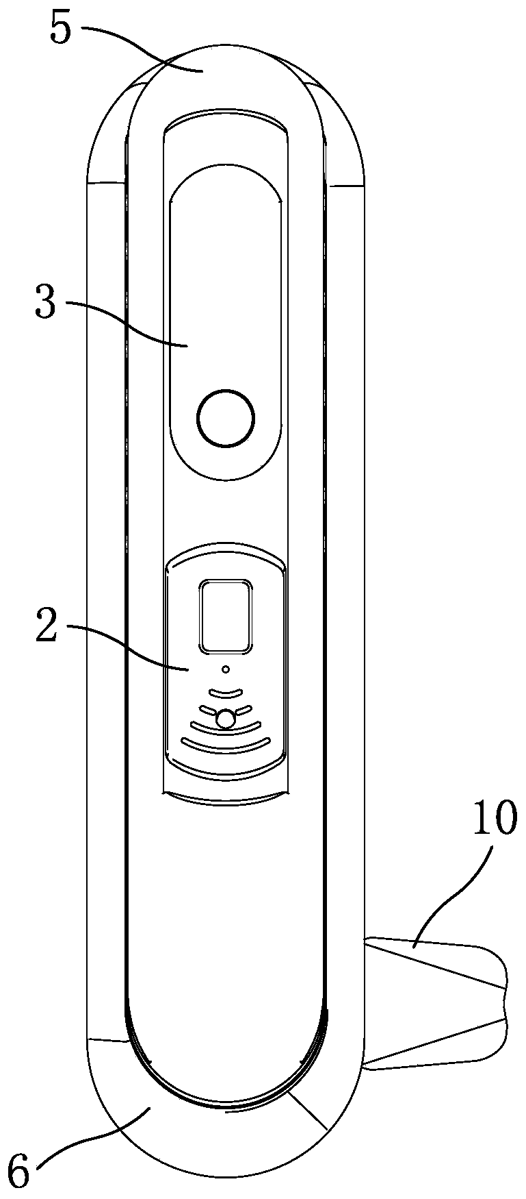
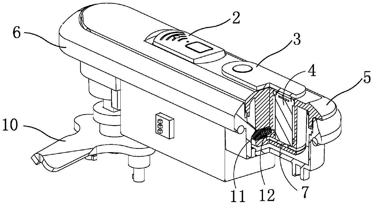
[0020] Now in conjunction with the accompanying drawings, the structure and use of the present invention will be further described. Such as Figure 1-Figure 4 shown, and Figure 5-Figure 8 As shown in the working structure principle of the wedge mechanism, the base 6 of the electronic lock is provided with a handle 5, a control circuit and a solenoid valve 8, and one end of the handle at one end of the base is connected with the deadbolt 10 through the rotating shaft 1, and the handle and the rotating shaft Hinged, the other end of the handle is fastened with the base; the panel of the base is provided with an ID card reader 2, the card reader end of the ID card reader protrudes from the handle, the ID card reader is connected to the control circuit through a line, and the handle is connected to the base The fastening end bottom of the seat is provided with a sliding lock body bolt 7, the moving iron core of the electromagnetic valve is opposite to the lock body bolt, and the...


PUM


Abstract

The invention relates to a bevel wedge type electric lock of construction control and a using method thereof. The bevel wedge type electric lock is designed for solving the technical problems that a latch body is long, prone to damaging and clamping, poor in prying-resistant property and stability and inconvenient to produce, assemble and correct due to the poor structural design of a similar product. A handle, a control circuit and an electromagnetic valve are installed in a pedestal of the electric lock. The key points are that an ID card reader is installed on a panel of the pedestal, a slidable lock latch is installed at the bottom of the fastening end of the handle and the pedestal, a movable iron core of the electromagnetic valve is opposite to the lock latch, and the handle on the opposite position is provided with bevel wedge sliding blocks which are symmetrically arranged; a sliding block spring is installed between the bevel wedge sliding blocks, and a bevel wedge protrusion is installed on the inner side, corresponding to the ends of the bevel wedge sliding blocks, of the pedestal; and an L-shaped hook end of the lock latch is located on the sliding block spring between the bevel wedge sliding blocks, and the hook end of the lock latch is opposite to the movable iron core of the electromagnetic valve. The rear portion of the movable iron core of the electromagnetic valve also stretches out of a valve body, and the movable iron core of the end abuts against a constantly power-on movable iron core of a constantly power-on electromagnetic valve.

Description

technical field [0001] The invention relates to a control device screen and a door lock for a control cabinet, which is a wedge-type electronic lock and a use method thereof. Background technique [0002] A door lock is a device used to lock the door. It is generally divided into mechanical, electric, combination locks, etc. Some of the door locks are used for metal cabinet doors. This type of cabinet lock is mainly used for power distribution cabinets, filing cabinets, and lockers. The opening and closing of metal cabinet doors; and the electronic locks used for the above cabinet doors generally require strong or weak electricity to provide unlocking power; according to the different ways of electronic induction, they are divided into electronic combination locks and electronic induction locks. The electronic locks used for cabinet doors basically use electromagnets to control the closing and opening of the mechanical parts to complete the unlocking and locking tasks of the...

Claims


Application Information

Patent Timeline
Patent Type & Authority Patents(China)
IPC IPC(8): E05B47/00E05B3/00E05B15/00E05B17/00G07C9/00
CPCE05B3/00E05B15/00E05B17/002E05B47/0001G07C9/00182
Inventor 姚春良
Owner 宁波生久科技有限公司
Why Eureka
Try Eureka