Design method and device for lubricating oil system for air blower and auxiliary equipment of compressor

A technology of lubricating oil and compressor, applied in the field of lubricating oil system, to achieve the effect of avoiding duplication of work and preventing data leakage

Active Publication Date: 2017-06-20
SHENYANG BLOWER WORKS GROUP CORP
9 Cites 1 Cited by

AI-Extracted Technical Summary

Problems solved by technology

[0002] The existing technology lacks a technology that integrates the lubricating oil syst...

Abstract

The invention provides a design method for a lubricating oil system for an air blower and auxiliary equipment of a compressor. The design method comprises the following steps: step 10, determining design input parameters of the lubricating oil system, wherein the design input parameters comprise the item information, the industry design standards, the air blower lubricating equipment list, the physical properties of lubricating oil, the lubricating oil flow pressure, the lubricating oil supply pressure, the energy accumulator placement position, the compressor running-down time, the lubricating oil system components, and the public conditions of engineering; and step 20, designing the lubricating oil system for the air blower and the auxiliary equipment of the compressor according to the design input parameters. By adoption of the design method provided by the invention, the work for designing the lubricating oil system for the large-scale air blower and the auxiliary equipment of the compressor can be simplified and intelligentized.

Application Domain

Technology Topic

Image

  • Design method and device for lubricating oil system for air blower and auxiliary equipment of compressor
  • Design method and device for lubricating oil system for air blower and auxiliary equipment of compressor
  • Design method and device for lubricating oil system for air blower and auxiliary equipment of compressor

Examples

  • Experimental program(1)

Example Embodiment

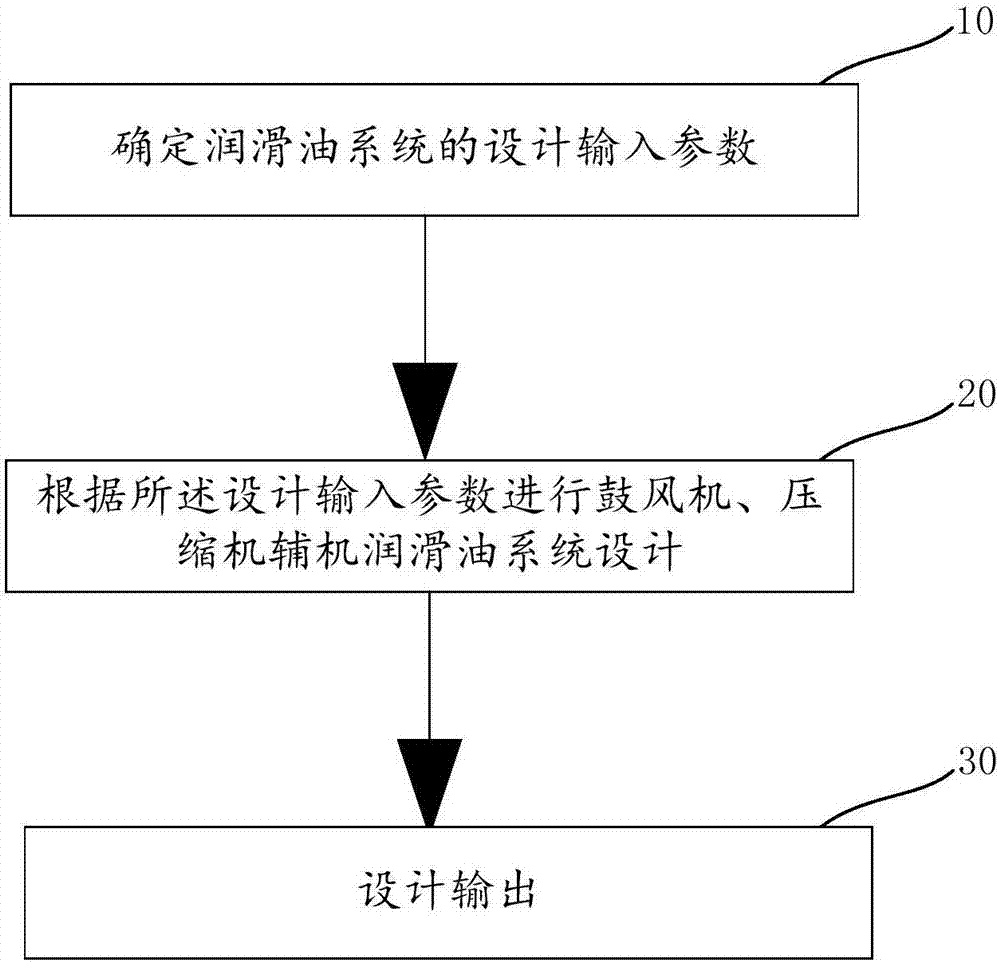
[0022] see figure 1 , the design method of the lubricating oil system for the blower and the auxiliary compressor of the compressor provided by the embodiment of the present invention includes:
[0023] Step 10. Determine the design input parameters of the lubricating oil system; the design input parameters include project information, industry design standards, list of blower fan lubrication equipment, lubricating oil physical properties, lubricating oil flow pressure, lubricating oil supply pressure, accumulator place, compressor idle time, components of the lubricating oil system and common engineering conditions; the lubricating oil system is used for the blower and compressor auxiliary.
[0024] Among them, the project information includes user name, project address, project name, project number, contract number, quotation number, device name, version information, design, proofreading, audit: output agreement for purchased parts, instrument control contact form, consumption table, device Relevant user information of the table, API614 data sheet, gas station price list, and gas station manual;
[0025] Industry design standards include standards set by the fourth and fifth editions of API614 for lubricating oil systems, GB and API standards for lubricating oil system components, GB/T 151, GB/T 28574, GB/T10886, GB/T T5171, API6144 TH , API614 5 TH , API676, API610, API526, etc.
[0026] The list of blower fan lubrication equipment includes compressor thrust bearings, compressor rolling bearings, gearboxes and superchargers.
[0027] The physical properties of the lubricating oil include viscosity, specific heat and density; the required flow and pressure of the lubricating oil include the flow and pressure of the lubricating oil.
[0028] The selection of components of the lubricating oil system is to determine the components of the lubricating oil system; the project common conditions refer to the basic design conditions of the cooling water, nitrogen source, low-voltage electricity and other projects, such as the cooling water inlet pressure, temperature, return water pressure, Temperature, nitrogen temperature and pressure, low voltage electric voltage, frequency, number of phases, steam pressure, temperature, etc.
[0029] Step 20: Design the lubricating oil system of the blower and the auxiliary engine of the compressor according to the design input parameters; the design of the lubricating oil system of the auxiliary engine of the blower and the compressor includes determining the pipe diameter through the calculation of the flow rate, determining the output pressure of the oil pump through the calculation of the pressure drop, Oil pump design, pipeline design pressure, oil filter design, high-level oil tank design, accumulator design, thermal calculation, fuel tank design, heater design, safety valve calculation design.
[0030] Wherein, determining the pipe diameter through flow velocity calculation in step 20 includes:
[0031] First according to step 10 the industry design standard (ie API614 4 TH or API6145 TH ) specified flow velocity range and lubricating oil amount to calculate the pipe diameter, the calculation formula is as follows:
[0032]
[0033] Among them, d is the pipe diameter, q is the amount of lubricating oil, and v is the flow rate of lubricating oil;
[0034] Then adjust the diameter of the pipeline adjacent to the above formula d, and perform an iterative check on the flow rate to adjust to the flow rate range specified by the industry design standard.
[0035] Wherein, determining the output pressure of the oil pump through pressure drop calculation in step 20 includes:
[0036] The components that generate pressure drop are determined; the components that generate pressure drop include pipes, valves, oil cooler pipe, oil filter core and temperature control valve;
[0037] Perform algebraic sum operation on the maximum design pressure drop generated by the components that generate pressure drop during operation, that is, the total pressure drop ΔP from the oil pump outlet to the lubricating oil supply port;
[0038] Calculate the algebraic sum of the lubricating oil supply pressure and the total pressure drop ΔP in step 10 to obtain the minimum output pressure of the oil pump;
[0039] A pressure greater than the minimum output pressure of the oil pump is determined as the oil pump output pressure Pnorm.
[0040] Wherein, the oil pump design described in step 20 includes the design of lubricating oil pump and accident oil pump;
[0041] The lube oil pump design includes:
[0042] The lube oil pump design includes:
[0043] The oil pump output pressure P norm , at 65±5℃, adjust the coefficient of the total oil volume of lubricating oil according to the provisions of API614, so as to determine the minimum output flow of the oil pump as Q 0;
[0044] Determine greater than and closest to Q 0 The model of the oil pump is used as the selected lubricating oil pump, according to the output pressure P of the oil pump norm Determine the output flow Q at 65±5℃ 1;
[0045] Calculate the pressure P in the open state of the safety valve PSV , P PSV =max[(Pnorm+0.17), 1.1×Pnorm], and according to the P PSV Determine the output flow Q at the lowest temperature of the lubricating oil system 2;
[0046] Calculate the pressure P in the 100% fully open state PSV全开 , P PSV全开 =1.1×P PSV , and according to the P PSV全开 Determine the output flow Q at the lowest temperature of the lubricating oil system 3;
[0047] According to P normThe adjusted value of the coefficient and the adjusted value of the PPSV full-open coefficient take the maximum value to determine the power PM of the lubricating oil pump drive motor, PM=max[Pnorm×N, PPSV full-open×N], where the value of the N coefficient depends on Pnorm and PPSV is fully open. For example, when Pnorm is less than 5KW, N is 1.25; when Pnorm is greater than 5KW and less than 10KW, N is 1.2; when Pnorm is greater than 10KW and less than 50KW, N is 1.15; when Pnorm is greater than 50KW, N is 1.1.
[0048] The oil pump product sample contains the data table of pressure flow Q and the curve graph fitted by each discrete point. The value of Q0 is used to select Q1, and the values ​​of Q1, Q2, and Q3 can be obtained through the data table or graph using Pnorm, P PSV , P PSV全开 to obtain.
[0049] The accident oil pump design includes:
[0050] According to the function of the accident oil pump, determine the pressure P' and oil quantity required for the accident state; the functions of the accident oil pump include the use of accident oil supply, the cleaning of steam turbine impellers and the cooling of cranking;
[0051] At the said P', 65±5℃, according to the provisions of API614, adjust the coefficient of the accident oil quantity, so as to determine the minimum output flow of the oil pump as Q'0;
[0052] Determine the oil pump model larger than and closest to Q'0 as the selected accident oil pump, and determine the output flow Q'1 at 65±5°C according to the oil pump output pressure P';
[0053] Calculate the open state pressure P' of the safety valve PSV =max[(P'+0.17), 1.1×P'], and according to the P' PSV Determine the output flow Q’ at the lowest temperature of the lubricating oil system 2;
[0054] Calculate the pressure P' in the 100% fully open state PSV全开 =1.1×P’ PSV , and according to the P' PSV全开 Determine the output flow Q’ at the lowest temperature of the lubricating oil system 3;
[0055] According to the adjusted value of the P' coefficient and the adjusted value of the P'PSV coefficient, take the maximum value to determine the power PM' of the driving motor of the lubricating oil pump;
[0056] PM=max[P′×N, P′PSV fully open×N], where the value of the N coefficient depends on P′ and P′PSV.
[0057] The oil pump product sample has the data table of pressure flow Q and the curve graph fitted by each discrete point. The value of Q'0 is to select Q'1, and the values ​​of Q'1, Q'2, and Q'3 can pass the data. P'norm, P' for table or graph PSV , P' PSV全开 to obtain.
[0058] Wherein, the pipeline design pressure in step 20 includes
[0059] According to the components of the lubricating oil system in step 10, determine that the oil pump is a screw pump, a gear pump or a centrifugal pump;
[0060] When it is a screw pump or a gear pump, the pipeline design pressure Pd=Pnorm+max (Pnorm×0.2, 0.3);
[0061] When it is a centrifugal pump, the pipeline design pressure Pd=Pnorm+0.1.
[0062] Wherein, the oil filter design described in step 20 includes the design of lubricating oil filter, control oil filter and accident oil filter;
[0063] The design of the lubricating oil filter is to determine the number of filter elements of the lubricating oil filter, and the number of filter elements of the lubricating oil filter is n L =(a×QL/Qf) rounded up, the a is the load, the Q f is the flow rate of the filter element under the maximum differential pressure state, the Q L is the total amount of lubricating oil in the lubricating oil flow pressure in the step 10;
[0064] The control oil filter design includes determining the number of filter elements of the control oil filter, the number of filter elements n of the control oil filter C =(a×Q control/Qf) round up, the a is the load, the Q f is the flow rate of the filter element under the maximum differential pressure state, the Q 控 is the total oil volume of the control oil in the lubricating oil flow pressure in the step 10;
[0065] The accident oil filter includes determining the number of filter elements of the accident oil filter. The number of filter elements of the accident oil filter nE=(a×QE/Qf) is rounded up, the a is the load, and the Qf is the filter The flow rate of the filter element under the maximum differential pressure state, the Q E is the total oil quantity of the control oil in the accident oil flow pressure in the step 10.
[0066] Wherein, the high-level fuel tank design described in step 20 includes:
[0067] Determining the accident volume V 1 , the accident volume V 1 =T 1 ×0.5×Q L; The T1 is the input compressor idling time or the accident oil supply time required by the project information, and the Q L is the total amount of lubricating oil;
[0068] Determine the volume of the high-level fuel tank, which is greater than V1.
[0069] Wherein, the design of the accumulator in step 20 includes:
[0070] Determine the minimum volume V of cold oil required by the accumulator min , the Vmin=ΔV×(P1/P0)^(1/g)/1-(P1/P2)^(1/g);
[0071] Determine the maximum volume V of cold oil required by the accumulator max , the Vmax=Vmin×Tmax/Tmin;
[0072] Determine the oil volume ΔV, the ΔV=4×QL;
[0073] the P 1 The minimum system pressure for the lubricating oil system, the P 2 Accumulator inlet pressure for standby pump startup, the P 0 is the effective inflation pressure, the g is the gas adiabatic coefficient, the T min Minimum temperature for accumulator pre-charge gas, the T max is the maximum temperature of the medium when the lubricating oil system is running; the Q L is the total amount of lubricating oil;
[0074] According to V max Round up the value to select the accumulator engineering volume. In order to ensure accuracy, the actual oil displacement is iteratively calculated using the selected accumulator engineering volume for verification.
[0075] Among them, the thermal calculation in step 20 is to use the capture window handle and COM component handle technology, which can convert the basic software data (for example, the medium of the shell side and the pipe side, and the temperature and pressure of the inlet and outlet of the medium, the maximum design pressure respectively). drop, the number of baffles, cutting rate and other structural data in the check mode) are output to the industry software HTRI, use HTRI to perform thermal calculations, and capture the calculation results of HTRI, so as to obtain water consumption, cooling water speed, area margin.
[0076] Wherein, the fuel tank design in step 20 is to adjust the data according to the "design criteria" in "design of high-level fuel tank" and "design input". First, the volume of the high-level fuel tank and design criteria are preliminarily calculated. Preliminary calculations include: if you choose a petrol station of API614 standard, then the preliminary calculation of the fuel tank volume Q’=(T1×0.5+8+1)×Q L , the T1 is the high fuel tank accident fuel supply time, the Q L is the total amount of lubricating oil. If the non-API614 standard gas station is selected, then Q'=A×Q L , where A can be entered manually.
[0077] Secondly, when the result in "API614 Volume Check" does not meet the "free area of ​​the fuel tank should be 60 square centimeters per liter per minute for normal flow" specified in API614 (ignore this step if API614 is not selected in the design standard), pass the lubricating oil Adjust the amount of oil cushion. When the result passes the "API614 volume check" and the space rate is controlled at 5% to 10%, the current design is reasonable. Otherwise, it is necessary to change the design volume of the fuel tank and the amount of cushion oil for another iterative calculation.
[0078] Wherein, the heater design in step 20 includes electric heater design or steam heater design; the design includes determining the heat Qa required for heating the oil, the heat Qb exchanged between the side plate and the outside world, the heating temperature difference ΔT, and the minimum power of the electric heater. , logarithmic average temperature ΔTm, heat exchange per unit time Qc and heat exchange area S1;
[0079] The Qa=V4×γ×Cp×ΔT,
[0080] The Qb=S×Ks×T×ΔT,
[0081] The ΔT=T2-T1, where Cp is the specific heat of the lubricating oil, γ is the lubricating oil density, T is the heating time specified by the industry design standard, T 1 is the minimum ambient temperature, T 2 is the lowest starting temperature, ΔT is the heating temperature difference, Ks is the heat exchange coefficient between the side plate of the fuel tank and the outside world, S is the surface area of ​​the side of the fuel tank and V4 is the fuel injection volume of the fuel tank;
[0082] The electric heater minimum power N heater =1.15×(Qa+Qb)/T/1000×γ;
[0083] The logarithmic mean temperature ΔTm is calculated by the following formula:
[0084] ΔT1=T3-T1,
[0085] ΔT2=T3-T2,
[0086] ΔTm=(ΔT1-ΔT2)/ln(ΔT1/ΔT2),
[0087] The heat exchange per unit time Qc=(Qa+Qb)/T,
[0088] The heat exchange area S 1 =Qc/(ΔTm×K),
[0089] Steam heater steam consumption Qs=1.25×Qc/K1,
[0090] Among them, Qc is the heat exchange per unit time, S1 is the heat exchange area, T3 is the saturated steam temperature, K1 is the vaporization heat of the saturated steam, and K is the heat transfer coefficient of the heater.
[0091] Wherein, the calculation and design of the safety valve described in step 20 includes the design of the lubricating oil safety valve and the design of the accident oil safety valve; wherein, the design of the lubricating oil safety valve includes determining the required flow passage area of ​​the safety valve and the displacement of the safety valve;
[0092] The required flow passage area of ​​the safety valve
[0093]
[0094] The safety valve displacement The γ is the lubricating oil density, q is, Pdr is the rated discharge pressure, Pb is the back pressure, the Kd is, Kw is, Kc is, and Kv is.
[0095]Step 30 , output the design determined in step 20 . In addition, it can also output outsourcing parts agreement, instrument control contact sheet, consumption table/device table, API614 data sheet, gas station price list and gas station manual.
[0096] see figure 2. The embodiment of the present invention provides a design device for a lubricating oil system of a blower and a compressor auxiliary machine, which includes a design parameter determination module 10', a design module 20' and a design output module 30'.
[0097] Wherein, the design parameter determination module 10' determines the design input parameters of the lubricating oil system; the design input parameters include project information, industry design standards, a list of lubricating equipment for blower fans, lubricating oil physical properties, lubricating oil flow pressure, lubricating oil supply Oil pressure, accumulator placement position, compressor idling time, components of lubricating oil system and engineering common conditions; the lubricating oil system is used for blower and compressor auxiliary equipment; the item information includes user name, item address, project name, project number and device name;
[0098] The industry design standards include standards set by the fourth and fifth editions of API614 for lubricating oil systems, and GB and API standards for lubricating oil system components; the lubricating oil system components
[0099] The blower fan lubrication equipment list includes compressor thrust bearings, compressor rolling bearings, gearboxes and turbochargers;
[0100] The physical properties of the lubricating oil include viscosity, specific heat and density; the required flow pressure of the lubricating oil includes the flow and pressure of the lubricating oil;
[0101] The selection of the components of the lubricating oil system is to determine the components of the lubricating oil system; the common conditions of the project refer to the basic conditions for the complete design of the cooling water, nitrogen source, low-voltage electricity and other projects;
[0102] The design module 20', according to the design input parameters, design the lubricating oil system of the blower and the auxiliary engine of the compressor; the design of the lubricating oil system of the blower and the auxiliary engine of the compressor includes determining the pipe diameter through the calculation of the flow rate, and determining the output of the oil pump through the calculation of the pressure drop. Pressure, oil pump design, pipeline design pressure, oil filter design, high oil tank design, accumulator design, thermal calculation, fuel tank design, heater design, safety valve calculation design.
[0103] The design output module 30' outputs the design generated by the design module 20, and can also output outsourcing parts agreement, instrument control contact sheet, consumption table/device table, API614 data sheet, gas station price list and gas station manual.
[0104] The design method and device for the lubricating oil system for the blower and the auxiliary compressor of the compressor provided by the present invention realize the simplification and intelligence of the design work of the lubricating oil system of the large blower and the auxiliary compressor of the compressor; Automatically complete the calculation, selection, data verification, design summary output, technical agreement generation of purchased parts, automatic filling of API614 data sheet, instrument control contact sheet output, and output of water and electricity consumption list of lubricating oil system. Lubricating oil system quotation (technical quotation), lubricating oil system manual and a series of complex tasks that need to be carried out in the product design process, thoroughly simplify complex data calculation, scheme selection, document output and other work, which can reduce the designer's work. Design pressure, while reducing the probability of errors, greatly improve design efficiency and reduce design costs. The invention is suitable for the design of lubricating oil system of API614 standard and non-API614 standard.

PUM

no PUM

Description & Claims & Application Information

We can also present the details of the Description, Claims and Application information to help users get a comprehensive understanding of the technical details of the patent, such as background art, summary of invention, brief description of drawings, description of embodiments, and other original content. On the other hand, users can also determine the specific scope of protection of the technology through the list of claims; as well as understand the changes in the life cycle of the technology with the presentation of the patent timeline. Login to view more.

Similar technology patents

Marine fuel oil pipeline oil-leakage emergency welding device and method

PendingCN112122864AShorten the timeAvoid duplication of effortWelding/cutting auxillary devicesAuxillary welding devicesFuel lineMarine fuel
Owner:HUDONG ZHONGHUA SHIPBUILDINGGROUP

Chain breakage detection device for traversing table

InactiveCN108665073ARealize remote maintenance functionAvoid duplication of effortInput/output for user-computer interactionTransmission systemsDrive motorInternet network
Owner:上海前孟计算机科技有限公司

Classification and recommendation of technical efficacy words

  • Prevent Data Leakage
  • Avoid duplication of effort

Method and apparatus for dynamically regulating visual angle of screen

ActiveCN101488326APrevent Data LeakageImprove convenienceCathode-ray tube indicatorsInstrumental componentsVisual rangeScreen viewing
Owner:HTC CORP

Secure storage device

ActiveCN104239820AAchieve securityPrevent Data LeakageInternal/peripheral component protectionLocal machineComputer hardware
Owner:POTEVIO INFORMATION TECH

Protection method and device for executable programs

ActiveCN103488919APrevent memory dumpsPrevent Data LeakageProgram/content distribution protectionData informationExecutable
Owner:BEIJING SENSESHIELD TECH

A method for dynamic control of animation operation process

InactiveCN101266693AAvoid duplication of effortImprove efficiencyAnimation3D-image renderingJava classesProgram logic
Owner:KONKA GROUP

Optimization method for processing multiple extreme values and multiple restricted problems in flight vehicle design

InactiveCN104750948AGuaranteed feasibilityAvoid duplication of effortSpecial data processing applicationsFlight vehicleDesign cycle
Owner:BEIJING INSTITUTE OF TECHNOLOGYGY

System and method for managing primitive attribute

Owner:FOXCONN NANJING SOFTWARE CO LTD +1

Coal mine underground multi-system data acquisition and transmission method and apparatus

InactiveCN105336146ASimplify construction complexityAvoid duplication of effortElectric signal transmission systemsCoalData information
Owner:TIANDI CHANGZHOU AUTOMATION +1
Why Eureka
Try Eureka