a display device

A technology for display devices and display areas, which is applied in the fields of instruments, computing, and optics, and can solve the problem that the area of ​​the light-transmitting area cannot be made small due to the limitation of process precision.

Active Publication Date: 2018-09-18
BOE TECH GRP CO LTD
View PDF5 Cites 0 Cited by
  • Summary
  • Abstract
  • Description
  • Claims
  • Application Information

AI Technical Summary

Problems solved by technology

[0004] In view of this, an embodiment of the present invention provides a display device to solve the problem that the area of ​​the light-transmitting region in the existing light filtering structure cannot be made small due to the limitation of process precision.

Method used


Image

  • a display device
  • a display device
  • a display device

Examples


Embodiment Construction

[0029] The specific implementation manner of the display device provided by the embodiment of the present invention will be described in detail below with reference to the accompanying drawings.

[0030] The thickness of each film layer and the shape and size of the region in the drawings do not reflect the true proportion of the display device, and the purpose is only to illustrate the content of the present invention.

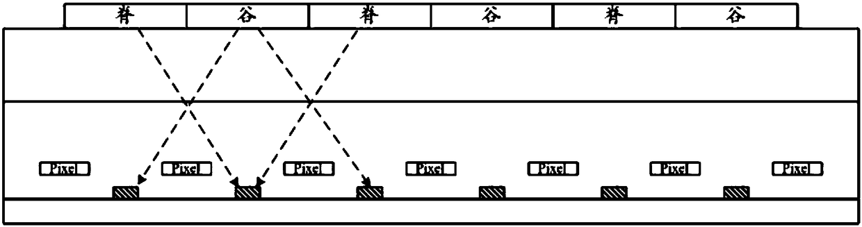
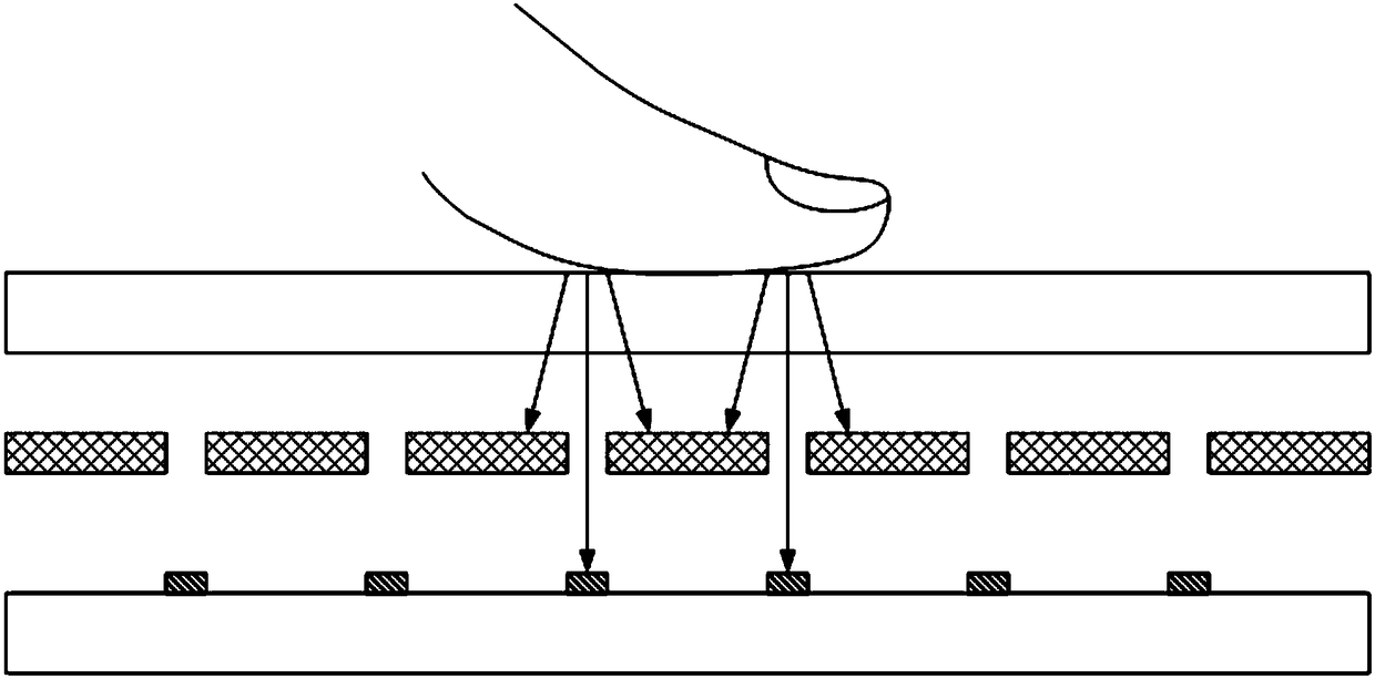
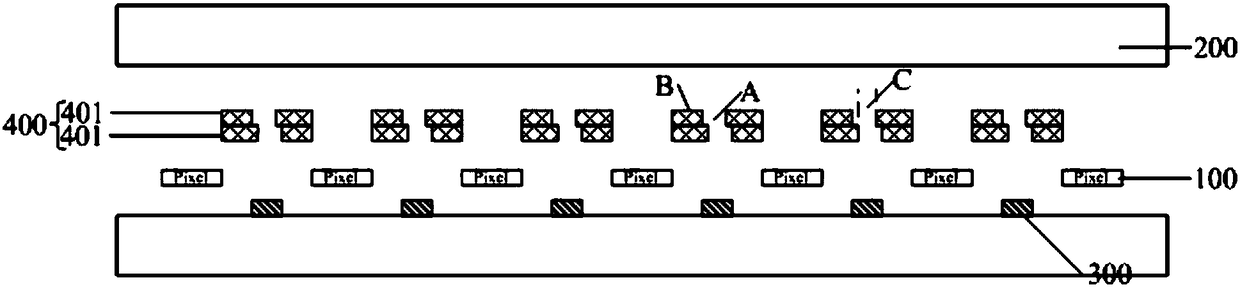
[0031] An embodiment of the present invention provides a display device, such as Figure 3a to Figure 3c As shown, it includes: a display panel with a plurality of pixel units 100, a protective cover 200 disposed on the light-emitting surface of the display panel, a plurality of photosensitive devices 300 disposed under the protective cover 200 for texture recognition, and disposed on A plurality of filter structures 400 between the protective cover 200 and the plurality of photosensitive devices 300; wherein,

[0032] Orthographic projections of the photose...


PUM


Abstract

The invention discloses a display device. The filter structure arranged between a protective cover plate and a plurality of photosensitive devices is changed to be composed of a plurality of filter layers stacked. Each filter layer has a light-transmitting area and a In the light-shielding area other than the light-transmitting area, the central positions of the light-transmitting areas of each filter layer are at least partially displaced, so that the orthographic projection of the light-transmitting area of ​​each filter layer on the display panel has an overlapping area, and the overlapping area The area of ​​is the light transmission area of ​​the filter structure. By adjusting the misalignment of the central position of the light-transmitting area of ​​each filter layer, the light-transmitting area of ​​the light-filtering structure can be reduced as required, so that the light-filtering structure is not affected by the precision of the manufacturing equipment, and the accuracy of optical fingerprint recognition is improved. In addition, reducing the light transmission area of ​​the filter structure as required can prevent the thickness of the display device from being affected by the filter structure being too thick while ensuring the collimation effect.

Description

technical field [0001] The present invention relates to the field of display technology, in particular to a display device. Background technique [0002] At present, the devices that realize the texture recognition function installed on display devices such as mobile phones are all in non-display areas such as the home button or the back of the display device, and the future development direction of display devices is ultra-thin, high color gamut, wide viewing angle and integrated Various sensing functions. When the optical sensor (Sensor) that realizes texture recognition is integrated inside the display panel, the distance between the Sensor and the finger contact surface will increase, causing the distance for the reflected light from the finger to reach the Sensor to increase, and the light reflected by the finger will reach the Sensor. Scattering occurs before the Sensor, such as figure 1 As shown, a single optical sensor receives fingerprint information of multiple v...

Claims


Application Information

Patent Timeline
Patent Type & Authority Patents(China)
IPC IPC(8): G02B5/22G06K9/00G06V40/13
CPCG02B5/22G06V40/13
Inventor 贾亚楠董学王海生吴俊纬刘英明许睿赵利军李昌峰秦云科郭玉珍顾品超韩艳玲
Owner BOE TECH GRP CO LTD
Why Eureka
Try Eureka