An oil-cooled, low-consumption inner rotor permanent magnet motor

A permanent magnet motor, inner rotor technology, applied in synchronous motors with stationary armatures and rotating magnets, magnetic circuits, electric components, etc., can solve the problem of insufficient use of thermal conductivity, increased motor oil friction loss, and decreased power density. and other problems, to achieve the effect of reducing harmonics, reducing oil friction loss, and improving power density

Active Publication Date: 2018-11-20
哈尔滨深能电机有限公司
View PDF4 Cites 0 Cited by
  • Summary
  • Abstract
  • Description
  • Claims
  • Application Information

AI Technical Summary

Problems solved by technology

First of all, when the rotor moves in the fluid, the non-smooth outer surface causes greater resistance, the oil friction loss of the motor increases, the efficiency decreases, and the power density of the entire system decreases
Secondly, the oil in the air gap of the existing oil-filled permanent magnet motor basically flows in the circumferential direction, and the axial flow is relatively small. The heat transfer mainly depends on heat conduction, and the good thermal conductivity of the oil is not fully utilized.

Method used


Image

  • An oil-cooled, low-consumption inner rotor permanent magnet motor
  • An oil-cooled, low-consumption inner rotor permanent magnet motor
  • An oil-cooled, low-consumption inner rotor permanent magnet motor

Examples


specific Embodiment approach 1

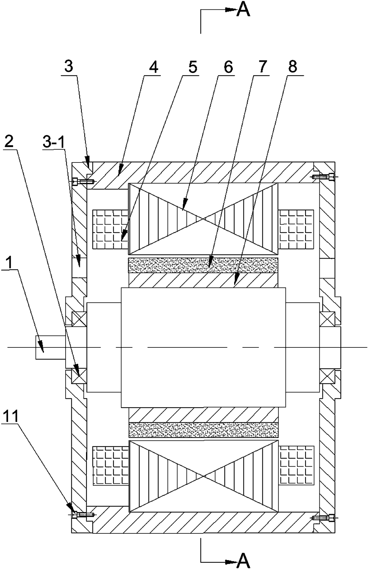
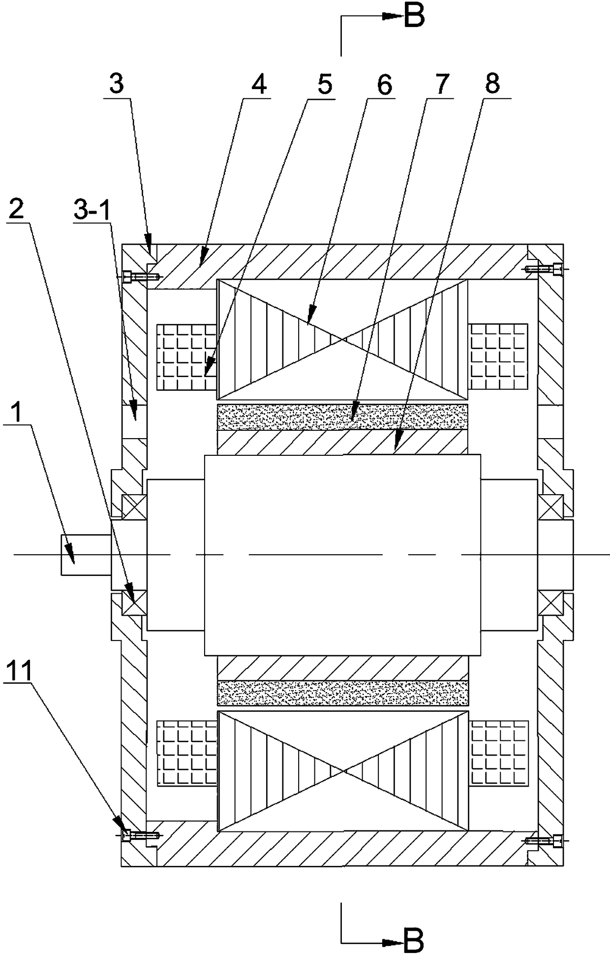
[0031] Specific implementation manner one: such as Figure 1~Figure 14 As shown, this embodiment records an oil-cooled, low-loss internal rotor permanent magnet motor, which includes a stator and a rotor. The stator includes a casing 4, a stator core 6, an insulating layer 9, and an axial key 10. , A plurality of stator coils 5 and two end covers 3; the rotor includes a rotor shaft 1, a rotor yoke 8, two bearings 2 and a plurality of magnetic steel 7; the rotor yoke 8 is fixed on the rotor shaft 1 On the outer circular surface, the outer circular surface of the rotor yoke 8 is located on the same circumference, and a plurality of magnetic steels 7 are arranged closely in sequence. The two ends of the rotor shaft 1 are each rotatably connected with the two end covers 3 through a bearing 2. The casing 4 rings are sleeved on the outer sides of the plurality of magnets 7, the casing 4 and the two end covers 3 are detachably fixedly connected by screws 11, and the outer rings of the...

specific Embodiment approach 2

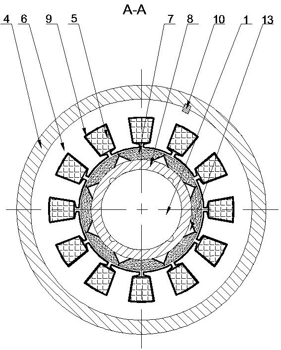
[0033] Specific implementation manner two: such as figure 2 with Figure 4 As shown, this embodiment will further explain the first embodiment. The inner corners 12 of the plurality of magnetic steels 7 and the outer circular surface of the rotor yoke 8 form a plurality of axial channels 13.

specific Embodiment approach 3

[0034] Specific implementation manner three: such as Picture 9 with Picture 10 As shown, this embodiment will further explain the first embodiment. The precession drainage groove 7-1 is a left-handed or right-handed precession drainage groove 7-1, and the left-handed or right-handed precession drainage groove The setting principle of 7-1 is: when the rotor is placed upright on a horizontal plane, the precession drainage groove 7-1 rotates counterclockwise and rises, which is left-handed precession drainage groove 7-1; Rotating and rising in the clockwise direction is the right-handed precession drainage groove 7-1, wherein the cross-sectional shape of the precession drainage groove 7-1 is rectangular, semicircular, triangular or trapezoidal.


PUM


Abstract

The invention provides an oil-cooling and low-loss internal rotor permanent magnetic motor, which belongs to the motor field and aims to reduce the oil friction loss, to improve the heat radiation performance, and further to increase the power density of a motor applied to an oil-immersed environment. The invention comprises a stator and a rotor. The stator comprises a housing, a stator iron core, an insulation layer, a shaft direction key, a plurality of stator coils and two end covers. The rotor comprises a rotor shaft, a rotor magnetic yoke, two bearings and a plurality of magnetic steels. According to the invention, the two sides of the inner round arc face of each magnetic steel are cut with inner angles. The outer round face formed by the plurality of magnetic steels is provided with a flow guiding groove along the shaft direction in a rotation manner. The inner round face of the rotor magnetic yoke is provided with inclined flow passing grooves in the shaft direction. The plurality of inclined flow passing grooves are symmetrically distributed around the round circumference. When the stator iron core is casted into shape directly, a plurality of back flow holes are supposed to be reserved on the yoke part or a plurality of back flow grooves are reserved at the back to provide a passage for oil to circulate inside the motor. In an oil-immersed high temperature environment, when such a motor is used, the power density can be increased, therefore, making the motor of great practical value.

Description

Technical field [0001] The invention relates to an inner rotor permanent magnet motor, belonging to the field of motors. Background technique [0002] In the design of permanent magnet motors, in order to reduce the harmonics of the air gap magnetic field, unequal air gap design schemes are often adopted. The outer surface formed by the magnetic steel bonded to the rotor yoke is not a smooth cylindrical surface (such as Figure 15 Shown), but there is a bump. In some working environments, the motor runs in oil and is filled with oil. Compared with the motor running in air, it will cause special problems. First of all, when the rotor moves in the fluid, the non-smooth outer surface causes greater resistance, the motor's oil friction loss increases, the efficiency decreases, and the power density of the entire system decreases. Secondly, the oil in the air gap of the existing oil-filled permanent magnet motor basically flows in a circumferential direction, and the axial flow is sma...

Claims


Application Information

Patent Timeline
Patent Type & Authority Patents(China)
IPC IPC(8): H02K9/19H02K1/27H02K1/32H02K1/20H02K21/14
CPCH02K1/20H02K1/278H02K1/32H02K9/19H02K21/14
Inventor 徐永向刘铭传邹继斌肖利军
Owner 哈尔滨深能电机有限公司
Why Eureka
Try Eureka