Oil cooling low consumption external rotor permanent magnetic motor

A permanent magnet motor and outer rotor technology, applied in the direction of magnetic circuits, electromechanical devices, electrical components, etc., can solve the problems of insufficient use of thermal conductivity, increased motor oil friction loss, decreased power density, etc., to achieve harmonic reduction, The effect of increasing the oil intake and improving the power density

Active Publication Date: 2017-07-21
哈尔滨深能电机有限公司
View PDF4 Cites 9 Cited by
  • Summary
  • Abstract
  • Description
  • Claims
  • Application Information

AI Technical Summary

Problems solved by technology

First of all, when the rotor moves in the fluid, the non-smooth surface causes greater resistance, the oil friction loss of the motor increases, the efficiency decreases, and the power density of the entire system decreases
Secondly, the oil in the air gap of the existing oil-filled permanent magnet motor basically flows in the circumferential direction, and the axial flow is relatively small. The heat transfer mainly depends on heat conduction, and the good thermal conductivity of the oil is not fully utilized.

Method used


Image

  • Oil cooling low consumption external rotor permanent magnetic motor
  • Oil cooling low consumption external rotor permanent magnetic motor
  • Oil cooling low consumption external rotor permanent magnetic motor

Examples


specific Embodiment approach 1

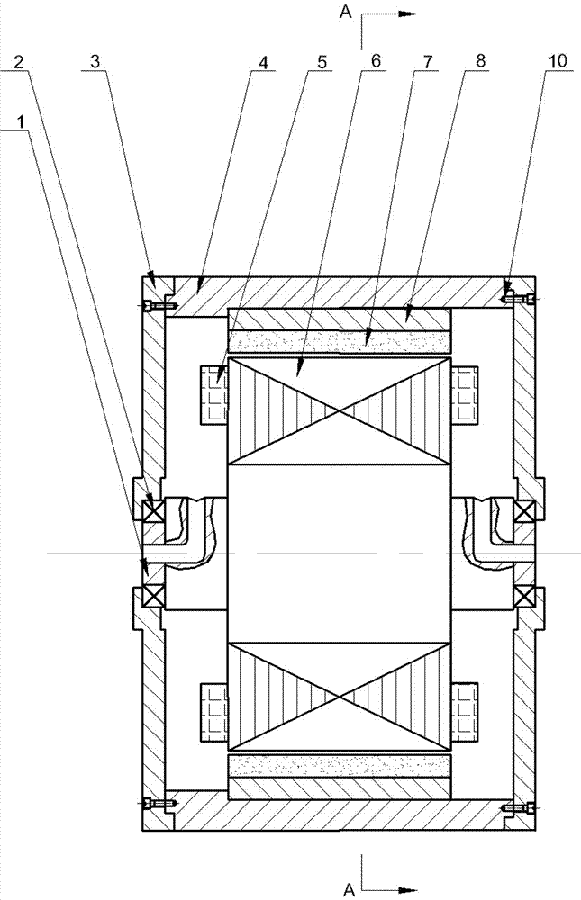
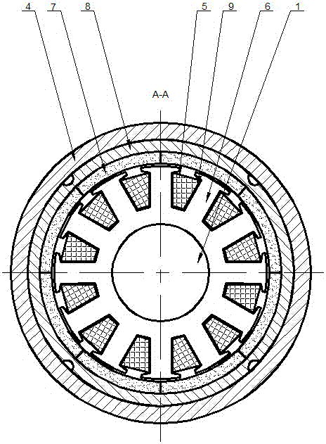
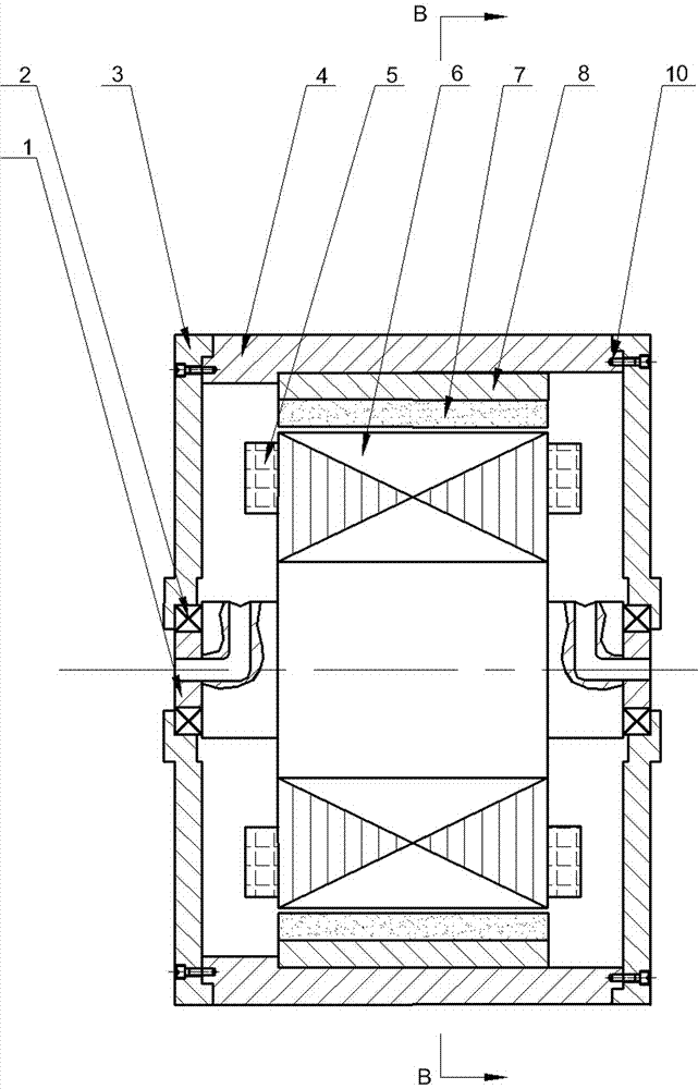
[0029] Specific implementation mode one: as Figure 1~Figure 13 As shown, this embodiment describes an oil-cooled, low-consumption external rotor permanent magnet motor, which includes a stator and a rotor. The stator includes a stator shaft 1, a stator core 6, an insulating layer 9 and a plurality of stator coils 5; the rotor includes a casing 4, a rotor yoke 8, two bearings 2, a plurality of magnetic steel 7 and two end covers 3; the rotor yoke 8 is fixed on the inner surface of the casing 4, The inner surface of the rotor yoke 8 is located on the same circumference, and a plurality of magnetic steels 7 are closely arranged in sequence. The two ends of the stator shaft 1 are respectively connected to the two end covers 3 through a bearing 2. The casing 4 rings are set On the outside of the plurality of magnetic steels 7, the housing 4 and the two end covers 3 are detachably fixedly connected by screws 10, and the inner ring of the plurality of magnetic steels 7 is fitted wit...

specific Embodiment approach 2

[0031] Specific implementation mode two: as Figure 5~Figure 9 As shown, this embodiment further describes the specific embodiment 1. The chamfered inner corners 11 of the plurality of magnetic steels 7 and the inner circular surface of the rotor yoke 8 form a plurality of axial channels 12 .

specific Embodiment approach 3

[0032] Specific implementation mode three: as Figure 10 and Figure 11 As shown, this embodiment will further explain the specific embodiment 1. The described screw-in drainage groove 7-1 is a left-handed or right-handed screw-in drainage groove 7-1, and the described left-handed or right-handed screw-in drainage groove 7-1 The setting principle of 7-1 is: when the rotor is placed upright on a horizontal plane, the screw-in drainage groove 7-1 rotates and rises in the counterclockwise direction, which is the left-handed screw-in drainage groove 7-1; Rotating upward in the clockwise direction is the right-handed spiraling drainage groove 7-1, wherein the cross-sectional shape of the spiraling drainage groove 7-1 is rectangular, semicircular, triangular or trapezoidal.


PUM


Abstract

The invention relates to an oil cooling low consumption external rotor permanent magnetic motor, belongs to the field of a motor and aims to reduce oil friction loss, improve heat radiation capability and improves power density applied to an oil-filled environment motor. The permanent magnetic motor comprises a stator and a rotor, wherein the stator comprises a stator shaft, a stator core, an insulation layer and multiple stator coils, the rotor comprises a casing, a rotor yoke, two bearings, multiple magnetic steels and two end covers. The permanent magnetic motor is characterized in that cutting of interior angles of two sides of an inner arc surface of each magnetic steel is carried out, an inner surface of a cylindrical structure formed by the multiple magnetic steels is axially provided with a screw-in drainage slot, an circular surface of the rotor yoke is axially provided with inclined over-current slots, and the multiple inclined over-current slots are symmetrically distributed circumferentially. The permanent magnetic motor is advantaged in that power density can be improved when the permanent magnetic motor is utilized under the oil filling high temperature environment, and great application values are realized.

Description

technical field [0001] The invention relates to an outer rotor permanent magnet motor, which belongs to the field of motors. Background technique [0002] In the design of permanent magnet motors, in order to reduce the harmonics of the air gap magnetic field, a design scheme with unequal air gaps is often used. The surface formed by the magnetic steel bonded to the rotor yoke is not a smooth cylindrical surface (such as Figure 14 shown), but there is a bump. In certain operating environments, motors running submerged in oil and filled with oil pose particular problems compared to motors running in air. First of all, when the rotor moves in the fluid, the non-smooth surface causes greater resistance, the oil friction loss of the motor increases, the efficiency decreases, and the power density of the entire system decreases. Secondly, the oil in the air gap of the existing oil-filled permanent magnet motor basically flows in the circumferential direction, and the axial flow...

Claims


Application Information

Patent Timeline
Patent Type & Authority Applications(China)
IPC IPC(8): H02K1/27H02K1/28H02K9/19
CPCH02K1/278H02K1/28H02K9/19
Inventor 邹继斌刘铭传徐永向肖利军
Owner 哈尔滨深能电机有限公司
Why Eureka
Try Eureka