Dust removing device for optical lens and dust removing method of device

A technology of optical lens and dust removal device, which is applied in the direction of cleaning methods, chemical instruments and methods, and smoke and dust removal using gas flow, can solve problems such as unfavorable long-term development of the company, low dust removal efficiency, poor dust removal effect, etc., to shorten the non-dust removal. Duration, fast dust removal, good effect

Active Publication Date: 2017-06-23
ZHEJIANG SUNNY OPTICAL CO LTD
View PDF6 Cites 9 Cited by
  • Summary
  • Abstract
  • Description
  • Claims
  • Application Information

AI Technical Summary

Problems solved by technology

This kind of dust removal device only blows dust on one surface of the optical lens, the dust removal effect is poor, and the dust blown by the blower device may fall into the optical lens again
In addition, the dust removal efficiency of this dust removal device is low and the speed is slow.
[0003] In addition, with the increasing popularity of mobile phones, the production capacity of mobile phone lenses is also increasing, which makes more and more lenses that need to be dusted; however, most of the existing dust removal equipment is still a single dust removal of the lens, and the efficiency is relatively low. And the dust removal effect is poor. If you want to meet the increasing production capacity, you have to purchase dust removal equipment in large quantities, which increases the cost and is not conducive to the long-term development of the company.

Method used


Image

  • Dust removing device for optical lens and dust removing method of device
  • Dust removing device for optical lens and dust removing method of device
  • Dust removing device for optical lens and dust removing method of device

Examples


Embodiment Construction

[0040]In order to more clearly describe the embodiments of the present invention or the technical solutions in the prior art, the following will briefly introduce the drawings that are used in the embodiments. Apparently, the drawings in the following description are only some embodiments of the present invention, and those skilled in the art can also obtain other drawings according to these drawings without creative efforts.

[0041] When describing the embodiments of the present invention, the terms "vertical", "transverse", "upper", "lower", "front", "rear", "left", "right", "vertical", " The orientation or positional relationship expressed by "horizontal", "top", "bottom", "inner" and "outer" is based on the orientation or positional relationship shown in the relevant drawings, which are only for the convenience of describing the present invention and simplifying the description, and It is not to indicate or imply that the device or element referred to must have a particul...


PUM


Abstract

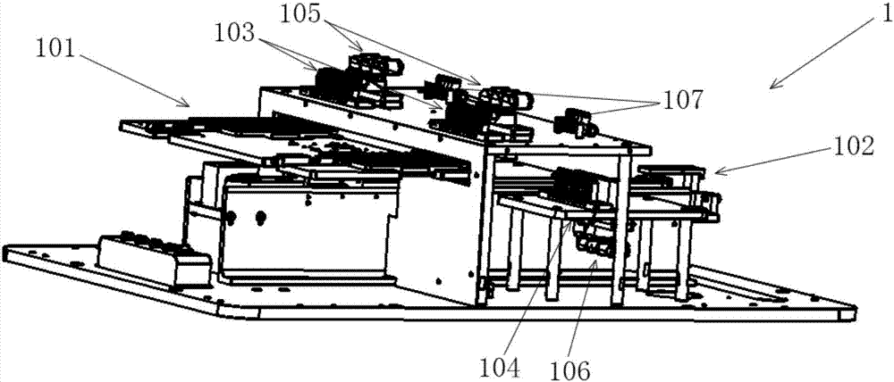
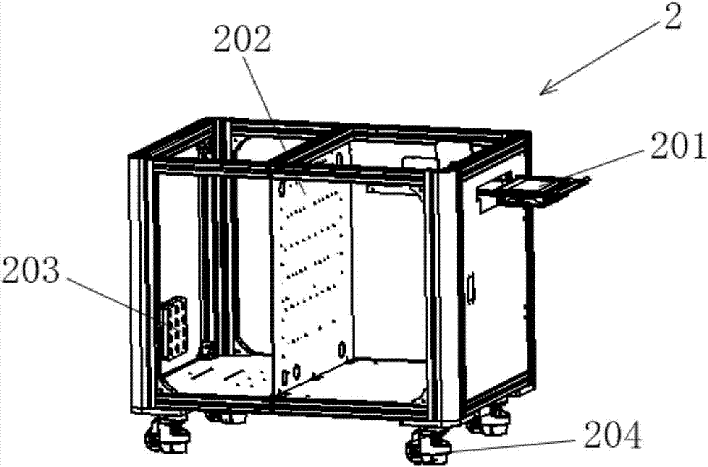
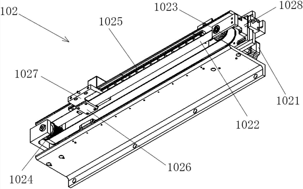
The invention relates to a dust removing device for an optical lens. The device comprises an upper device body and a lower device body; the upper device body comprises a lens accommodating unit, a driving unit, upper air injection units, a lower air injection unit, upper dust suction units, a lower dust suction unit and integrated air joints; the upper air injection units and the lower air injection unit are used for removing dust on the surface of the lens; the upper dust suction units and the lower dust suction unit are used for removing dust inside the lens; the integrated air joints are used for connecting the upper air injection units and the lower air injection unit with an air source through pipelines and connecting the upper dust suction units and the lower dust suction unit with an air suction device through pipelines; the upper air injection units and the upper dust suction units are arranged adjacently and are located above the lens accommodating unit; and the lower air injection unit and the lower dust suction unit are arranged adjacently, are located below the lens accommodating unit and are located underneath the upper air injection units and the upper dust suction units. The dust removing device is high in dust removing speed and high in dust removing efficiency, and the dust can be prevented from falling back.

Description

technical field [0001] The invention relates to a dust removal device and a dust removal method for an optical lens, in particular to a dust removal device and a dust removal method suitable for dust removal on the upper and lower sides of a mobile phone lens. Background technique [0002] Chinese patent 200710200842.1 discloses a dust removal device. The dust removal device is composed of a guiding platform, a driving part, a positioning part and an air blowing device. The blowing device is arranged on the guide rail on the guide platform below the positioning member, and the multiple optical lenses fixed in the positioning member are driven by the driving member to remove dust through the blowing device in sequence. This dust removal device only blows dust on one surface of the optical lens, and the dust removal effect is poor, and the dust blown up by the air blower may fall into the optical lens again. In addition, the dust removal efficiency of this dust removal devic...

Claims


Application Information

Patent Timeline
Patent Type & Authority Applications(China)
IPC IPC(8): B08B11/00B08B5/02B08B5/04B08B15/04
CPCB08B5/02B08B5/04B08B11/00B08B15/04
Inventor 蒋来洪洪凯黄浩滨叶小伟沈科良
Owner ZHEJIANG SUNNY OPTICAL CO LTD
Why Eureka
Try Eureka