An Inner-Cavity Optical Fiber Fabry-Perot Sensor for Slip Measurement

A sensor and optical fiber technology, applied in the field of sensors, can solve problems such as strong electromagnetic interference, and achieve the effects of not affecting measurement accuracy, high anti-shake and anti-vibration technology, and strong practicability

Active Publication Date: 2019-02-05
陈艺征
View PDF6 Cites 0 Cited by
  • Summary
  • Abstract
  • Description
  • Claims
  • Application Information

AI Technical Summary

Problems solved by technology

In the prior art, mechanical and electrical equipment are usually used for measurement, but these equipment usually have high requirements for the use environment, such as high temperature, low temperature, strong electromagnetic interference, etc. These occasions are not suitable for use

Method used


Image

  • An Inner-Cavity Optical Fiber Fabry-Perot Sensor for Slip Measurement
  • An Inner-Cavity Optical Fiber Fabry-Perot Sensor for Slip Measurement
  • An Inner-Cavity Optical Fiber Fabry-Perot Sensor for Slip Measurement

Examples


Embodiment 1

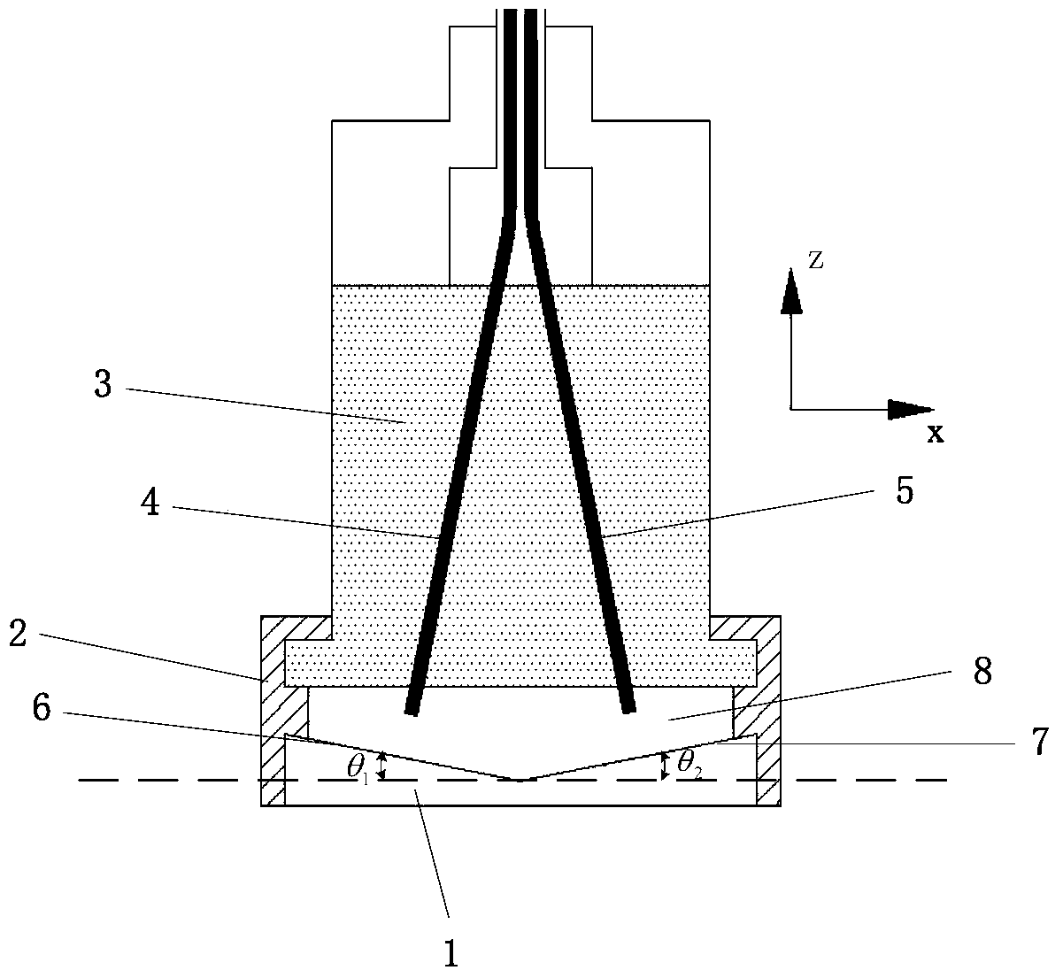
[0042] The invention provides a sensor for measuring slip in an inner cavity optical fiber Fabry Perot, such as figure 1 , figure 2 As shown, it includes a reflective slope 1, a sealed dust cover 2, a sensor body 3, a first optical fiber 4, and a second optical fiber 5, wherein:

[0043] The material of the reflective slope and the sensor body can be metal.

[0044] The sealed dustproof cover 2 is a flexible pipe body with a cavity 8 inside and two ends connected through. One end of the flexible pipe body is sealed and connected to the sensor body 3, and the other end is sealed and connected to the reflective slope 1;

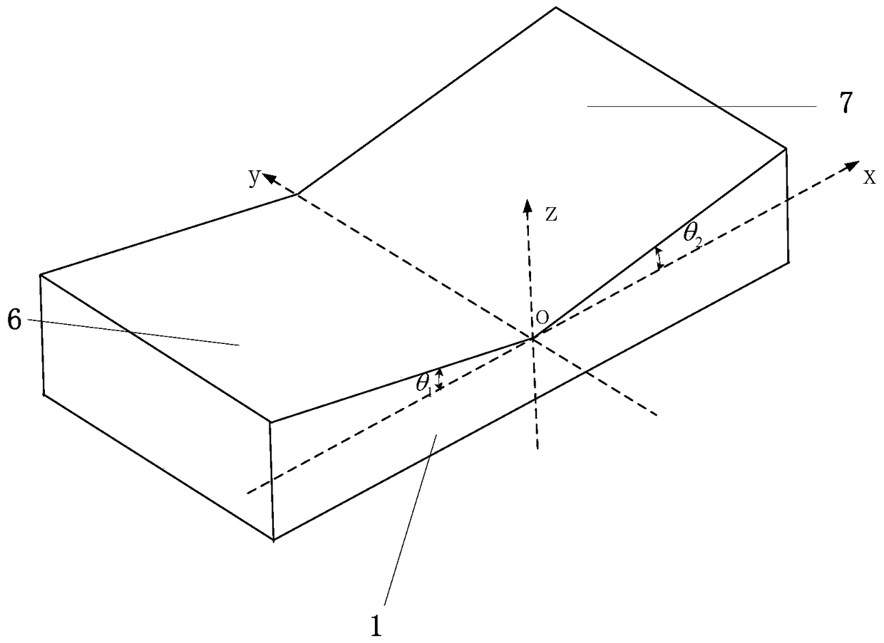
[0045] The bottom side of the reflective inclined surface 1 is a plane, and its upper side is provided with an inclination angle of θ with its bottom side plane. 1 The first inclined plane 6, the inclination angle is θ 2 The second inclined plane 7 is provided with a reflective surface on the upper side surfaces of the first inclined plane 6 and the second ...

Embodiment 2

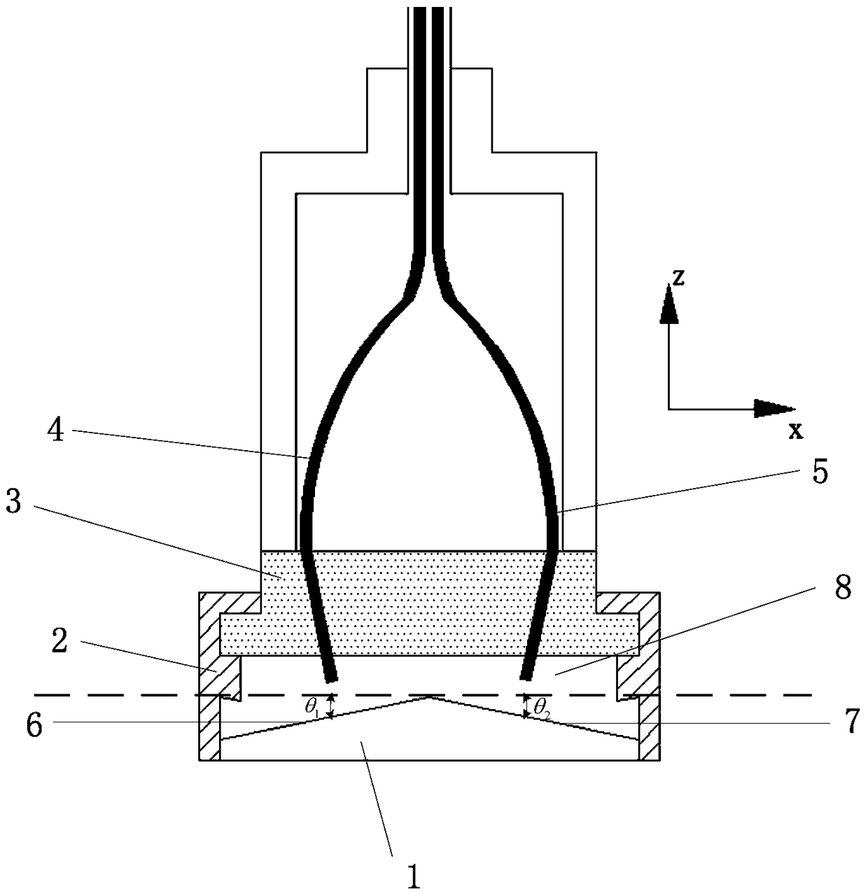
[0070] This embodiment has been improved on the basis of embodiment 1, as Figure 5 As shown, the specific improvements are as follows:

[0071] The first intersection line between the plane where the first slope 6 is located and the plane on the bottom side is perpendicular to the second intersection line between the plane where the second slope 7 is located and the plane on the bottom side,

[0072] and θ 1 ,θ 2 The condition that must be satisfied is sinθ 1 sinθ 2 ≠0.

[0073] Such as Figure 5 As shown, in actual use, in order to be able to simultaneously measure the slip in the x and y directions, the sensor uses two optical fibers and two reflective surfaces to measure the slip in one direction. During specific measurements (such as: To measure the displacement between object A and object B), you can grind a small groove with a flat bottom surface on object B (in fact, it does not necessarily have to be polished, there is another method, which is to weld the reflec...

Embodiment 3

[0076] This embodiment has been improved on the basis of embodiment 1, as Figure 6 As shown, the specific improvements are as follows:

[0077] The sensor also includes a third optical fiber, and the bottom of the third optical fiber is provided with a reflective end face, and the third optical fiber passes through the sensor body 3 and extends into the cavity 8;

[0078] The upper side of the reflective inclined surface 1 is also provided with an inclination angle of θ with its bottom side plane. 3 The third inclined plane 9 is provided with a reflective surface on the upper side surface of the third inclined plane 9;

[0079] And the first inclined plane 6, the second inclined plane 7 and the third inclined plane 9 must satisfy the condition that the determinant is not equal to 0, where (l 1 ,m 1 ,n 1 ), (l 2 ,m 2 ,n 2 ), (l 3 ,m 3 ,n 3 ) are respectively the normal vectors of the first, second and third slopes;

[0080] The optical axis of the third optical fi...


PUM


Abstract

The present invention provides the sensor for measuring the relative sliding between two interfaces based on the principle of EFPI. The sensor comprises two optical fibers and two slopes arranged on the reflective slope. Each surface of the slope is disposed with reflecting surface; and the bottom of each optical fiber is arranged with reflecting end surface. The reflecting surfaces are perpendicular to each of an optical axis of the fiber, thus the Fabry-Perot cavity is formed between reflective end surface and emitting surface to measure the sliding of object B relative to object A in a plane. A fiber and a slope can also be further added to measure the sliding of object B relative to object A in a three dimensional space. The sensor does not affected by the temperature and electromagnetic interference; and has the advantages of high accuracy, strong resisting interference capability and durability. The present sensor has wide application, especially suitable for precisely measuring the sliding and the temperature of the structure under static and dynamic or long-term loading and thus can evaluate the safety of the structures.

Description

technical field [0001] The invention relates to a sensor for measuring slippage, in particular to an inner-cavity optical fiber Fabry-Perot sensor for measuring slippage, which belongs to the field of sensors. Background technique [0002] Since the bonding effect between the steel plate and concrete is smaller than that of reinforced concrete in the steel plate concrete composite structure, the interface slip of the steel plate concrete composite structure is inevitable. The relative slippage of the interface is mainly due to the insufficient shear bond strength between the interface of concrete and steel plate, which reduces the combination effect, resulting in inconsistent deformation of the two. In the prior art, convenient mechanical and electrical equipment are usually used for measurement, but these equipment usually have high requirements for the use environment, such as high temperature, low temperature, strong electromagnetic interference, etc. These occasions are ...

Claims


Application Information

Patent Timeline
Patent Type & Authority Patents(China)
IPC IPC(8): G01D5/353
CPCG01B11/161G01B11/002
Inventor 陈艺征
Owner 陈艺征
Why Eureka
Try Eureka