Speed coupling slip frequency double-speed reducer

A reducer and slip technology, applied in the field of mechanical reducers, can solve the problems of not meeting the needs of use, difficult to couple multiple input speeds, and unable to effectively meet the needs of use, etc., and achieve the effect of compact structure, small volume and accurate slip.

Pending Publication Date: 2021-12-17
TONGJI UNIV
View PDF5 Cites 0 Cited by
  • Summary
  • Abstract
  • Description
  • Claims
  • Application Information

AI Technical Summary

Problems solved by technology

Since the reduction ratio of the gear is fixed, generally one input shaft corresponds to one output shaft, and it is not easy to achieve speed coupling between multiple inputs and multiple outputs
For a double-input reducer that needs to realize the speed coupling function, such as a planetary gear reducer, there is only one output shaft, which cannot meet all usage requirements
For application scenarios that need to generate two speeds at the same time, and the difference between the two speeds can be adjusted continuously, the existing various mechanical reducers cannot effectively meet the needs of use

Method used


Image

  • Speed coupling slip frequency double-speed reducer

Examples


Embodiment 1

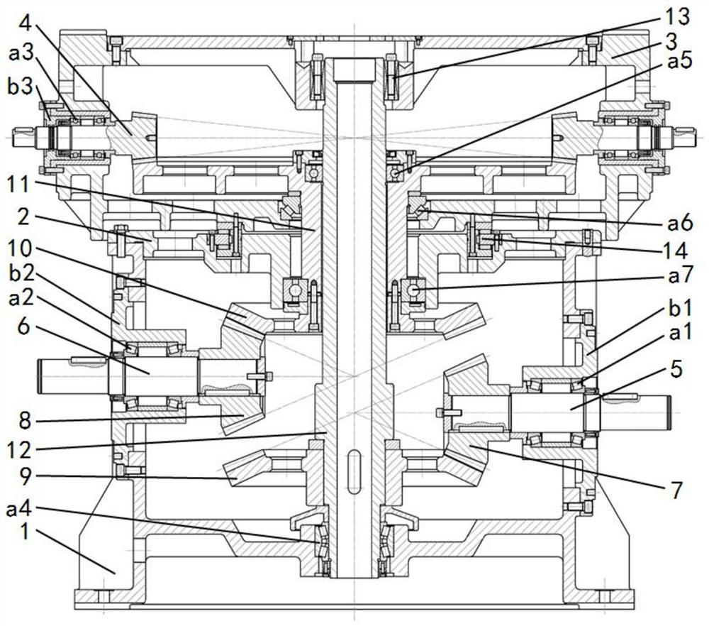
[0023] A slip two-speed reducer, such as figure 1 As shown, the reducer includes a revolution input shaft 5, an autorotation input shaft 6, an output shaft 4, a main shaft 12, a frame 1, an inner cover 2, a box cover 3, a bevel gear, a bearing, a gland, an expansion sleeve 13, and a flat key and screws. The frame 1 and the inner cover 2 are fixed, the box cover 3 rotates on the inner cover 2, the revolution input shaft 5 and the rotation input shaft 6 are connected to the frame 1 through the bearing and the gland, and the output shaft 4 is connected to the box through the bearing and the gland The cover 3 rotates together with the box cover 3, and the inside of the reducer is driven by three pairs of bevel gears. By separately controlling the rotational speeds of the revolution input shaft 5 and the autorotation input shaft 6, the continuous adjustment of the revolution speed, autorotation speed and slip of the output shaft 4 is realized.

[0024] Specifically, the frame 1 i...


PUM


Abstract

The invention relates to a speed coupling slip frequency double-speed reducer. The speed coupling slip frequency double-speed reducer comprises a rack (1) and an inner cover (2) fixed on the rack (1), a box cover (3) is rotatably arranged on the inner cover (2), an output shaft (4) is arranged on the box cover (3), a revolution input shaft (5) and a rotation input shaft (6) are arranged on the rack (1), the revolution input shaft (5) drives the box cover (3) to rotate, and the rotation input shaft (6) drives the output shaft (4) to rotate. Compared with the prior art, coupling of the revolution speed and the rotation speed at the output shaft end is achieved, and the difference (slip frequency) between the revolution speed and the rotation speed at the output shaft end can be continuously adjusted.

Description

technical field [0001] The invention relates to the technical field of mechanical reducers, in particular to a double-input, double-output, speed-coupled slip double-speed reducer. Background technique [0002] The reducer is used in various occasions that require speed regulation, especially the gear reducer that realizes transmission through gears. Because of its high transmission precision and reliable operation, it has been widely used. Since the gear reduction ratio is fixed, generally one input shaft corresponds to one output shaft, and it is not easy to realize speed coupling between multiple inputs and multiple outputs. For a double-input reducer that needs to realize the speed coupling function, such as a planetary gear reducer, there is only one output shaft, which cannot meet all usage requirements. For application scenarios that need to generate two speeds at the same time, and the difference between the two speeds can be adjusted continuously, the existing vari...

Claims


Application Information

Patent Timeline
Patent Type & Authority Applications(China)
IPC IPC(8): F16H1/22F16H57/021F16H57/023F16H57/038
CPCF16H1/222F16H57/021F16H57/023F16H57/038
Inventor 陈超田春吴萌岭陈茂林马天和
Owner TONGJI UNIV
Why Eureka
Try Eureka