Self-powered rotating device state monitoring device

A state monitoring device and rotating equipment technology, applied in the direction of measuring devices, circuit devices, battery circuit devices, etc., can solve the problems of cumbersome construction, short battery power supply life time, heavy power supply cable laying workload, etc., and achieve the effect of convenient installation

Inactive Publication Date: 2018-01-30
CHINA PETROLEUM & CHEM CORP +1
View PDF7 Cites 3 Cited by
  • Summary
  • Abstract
  • Description
  • Claims
  • Application Information

AI Technical Summary

Problems solved by technology

[0004] The present invention mainly solves the problems of heavy power supply cable laying workload, cumbersome construction, and short battery life in the prior art, and provides a new

Method used


Image

  • Self-powered rotating device state monitoring device
  • Self-powered rotating device state monitoring device
  • Self-powered rotating device state monitoring device

Examples


Example Embodiment

[0020] [Example 1]

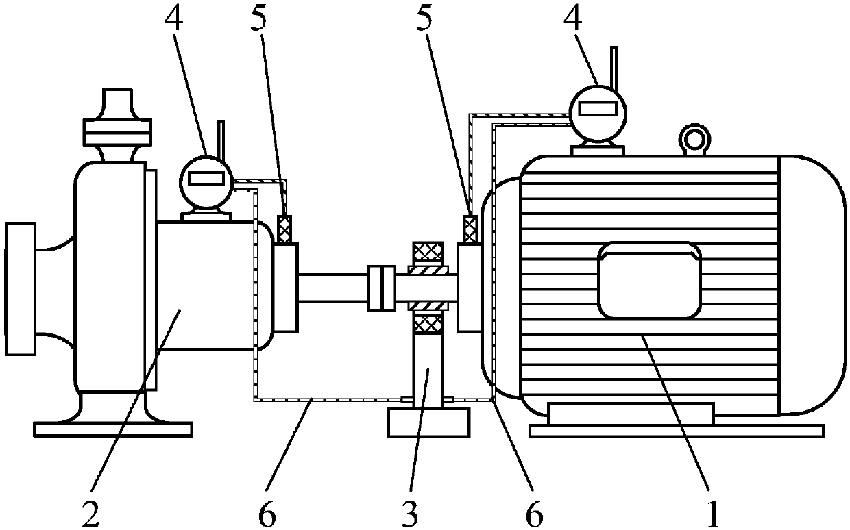
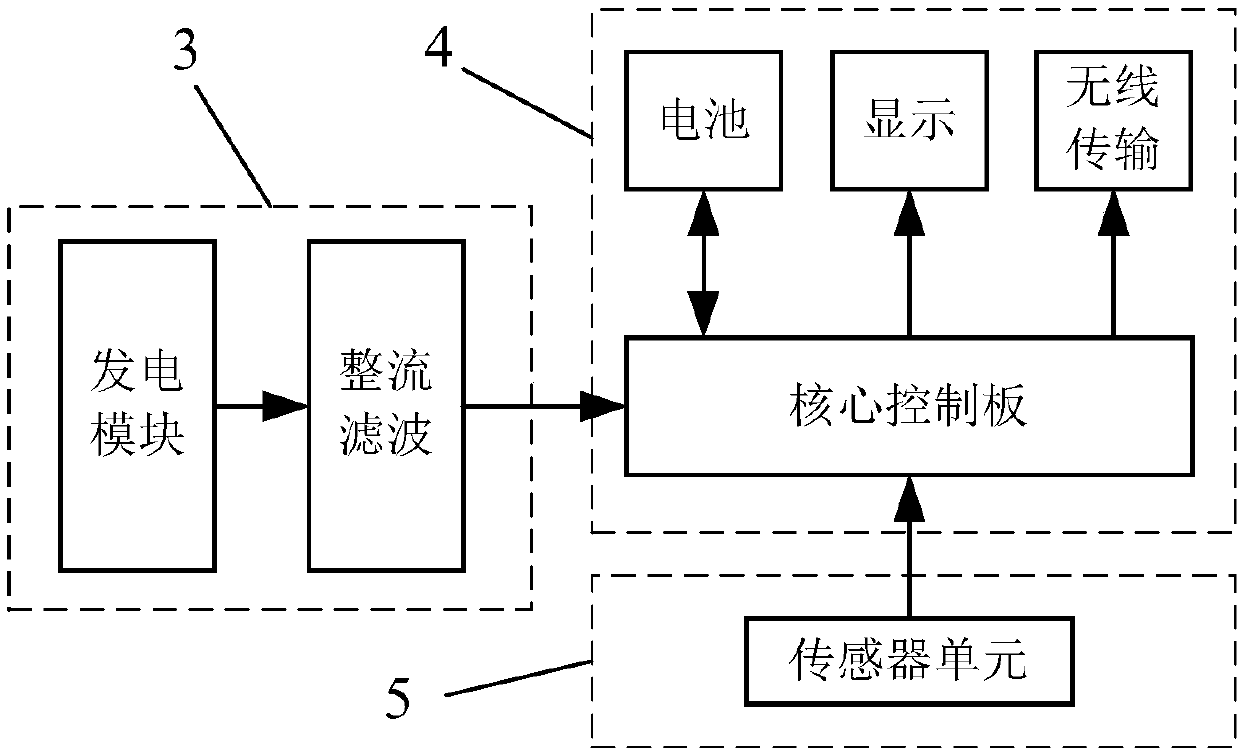
[0021] Such as figure 1 As shown, a self-powered rotating equipment condition monitoring device includes an electric power generation unit (3), a monitoring unit (4), a temperature and vibration integrated sensor (5), a power cord, and a signal transmission line. The power generation unit (3) is composed of The power generation module and the rectification filter module are composed of the motor drive end shaft rotation and the principle of electromagnetic induction to achieve power generation, and the rectification filter module converts it into a stable DC voltage to supply power to the monitoring unit (4), which has power management , Data collection and processing, data wireless transmission, result display function, to realize real-time collection of the temperature and vibration integrated sensor (5) signal, display and wireless transmission after processing, the temperature and vibration integrated sensor (5) is installed in the motor (1) as required )...

Example Embodiment

[0027] [Example 2]

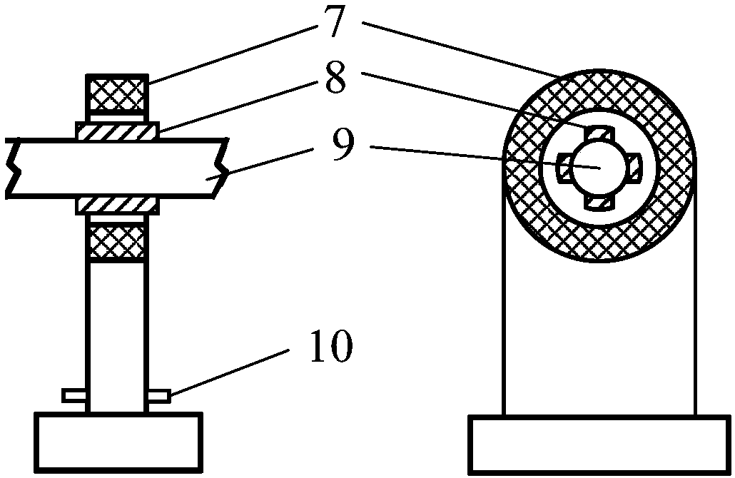
[0028] According to the conditions described in Embodiment 1, the induced voltage generated on the stator winding (7) is converted into a 24V DC voltage by the rectifier filter module, and the monitoring unit (4) is supplied with power through the power output terminal (10) and the power line (6). Install a temperature and vibration integrated sensor (5) on the pump (2) and the motor (1) close to the bearing. A monitoring unit (4) is fixed on the metal shell of the motor (1), and the pump (2) and the motor (1) are collected at the same time. The two sensor (5) signals on the) and the power output terminal (10) of the electric energy generating unit (3) respectively provide continuous electric energy for the monitoring unit (4) to realize real-time online monitoring of the operation status of the pump unit.


PUM


Abstract

The invention relates to a self-powered rotating device state monitoring device, and mainly solves the problem existing in the prior art that a power supply cable laying workload is large, construction is tedious, a battery is short in power supply endurance. The self-powered rotating device state monitoring device is composed of an electric energy generation unit (3), a monitoring unit (4), a temperature and vibration integrated sensor (5), and relevant power lines and signal transmission lines. The electric energy generation unit (3) is composed of a power generation module, a rectificationand filtering module and a stator winding center height adjusting mechanism. Power generation is achieved through rotation of motor driving end shaft and a electromagnetic induction principle, and thepower is converted into stable dc voltage by the rectification and filtering module, and then power is supplied to the monitoring unit (4), the technical scheme well solves the problem, and the self-powered rotating device state monitoring device can be applied to rotating device state monitoring.

Description

technical field [0001] The invention relates to a self-powered rotating equipment state monitoring device. technical background [0002] Rotating equipment such as motors and pumps are widely used in basic industries such as coal mines, petrochemicals, and electric power production, and play an important role in the production process. Due to the complex structure of the rotating equipment itself, the operating conditions are generally relatively harsh, and the failure rate in various equipment is relatively high. The quality of its operating status is directly related to the continuity and safety of enterprise production. Therefore, on-line monitoring and fault diagnosis of operating parameters such as vibration and temperature of rotating equipment such as motors and pumps are extremely important and necessary to ensure equipment reliability and production safety. [0003] At present, the condition monitoring devices installed on rotating equipment can be mainly divided i...

Claims


Application Information

Patent Timeline
IPC IPC(8): G01R31/34G01M99/00H02J7/14F04B51/00
Inventor 王世强刘全桢肖睿张云朋胡海燕张婷婷刘英杰高鑫
Owner CHINA PETROLEUM & CHEM CORP
Why Eureka
Try Eureka