Charging device for environmentally-friendly new energy electric car

A technology of electric vehicles and charging devices, which is applied in the direction of electric vehicle charging technology, electric vehicles, charging stations, etc., can solve problems such as slow plugging speed, lack of protection devices, and poor stability of charging plugging, so as to avoid electric shock hazards and improve Effects on Safety and Reliability

Active Publication Date: 2017-06-27
迈思普电子股份有限公司
View PDF6 Cites 26 Cited by
  • Summary
  • Abstract
  • Description
  • Claims
  • Application Information

AI Technical Summary

Problems solved by technology

The existing charging piles are relatively large in size and are placed next to the parking space, occupying a large land area. With the tightness of the parking space on the ground, the limited parking space will be more cramped after the charging pile is installed, and it will inevitably be blocked during use. Electric vehicles collid

Method used


Image

  • Charging device for environmentally-friendly new energy electric car
  • Charging device for environmentally-friendly new energy electric car
  • Charging device for environmentally-friendly new energy electric car

Examples


Embodiment Construction

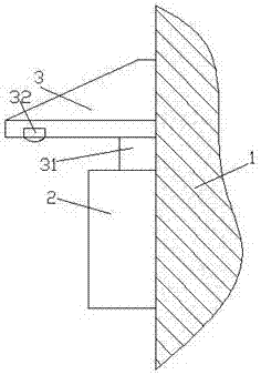
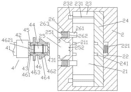
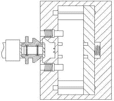
[0021] Such as Figure 1-Figure 6 As shown, a green new energy electric vehicle charging device of the present invention includes a charging box 2 fixed on the wall 1, and the inside of the charging box 2 is provided with an accommodation chamber 21, and the upper and lower sides of the accommodation chamber 21 Each is provided with a first sliding groove 23, and each of the first sliding grooves 23 is provided with a screw 231, the left end of the screw 231 is power connected with the motor 232, and the inner wall of the right side of the accommodation chamber 21 is provided with a first The sinking groove 22, the left inner wall of the accommodation cavity 21 is provided with a first conductive column 211, and the upper and lower sides of the accommodation cavity 21 are provided with the first sliding groove 23 extending into the upper and lower sides respectively and are connected by sliding fit. The moving slider 24, the moving slider 24 in the first sliding groove 23 is t...


PUM


Abstract

The invention discloses a charging device for an environmentally-friendly new energy electric car. The charging device comprises a charging box body fixed to a wall body, a containing cavity is formed in the charging box body, and first sliding grooves are formed in the upper side and the lower side of the containing cavity correspondingly. A screw is arranged in each first sliding groove, the left side end of the screw of each screw is in power connection with a motor, and a first sinking groove is formed in the inner wall of the right side of the containing cavity. First conductive pillars are arranged on the inner wall of the left side of the containing cavity, and the containing cavity is internally provided with a movable sliding block, wherein the upper side and the lower side of the movable sliding block extend into the first sliding grooves of the upper side and the lower side of the containing cavity correspondingly, and the movable sliding block is connected with the first sliding grooves in a sliding fit mode. The movable sliding block in the first sliding grooves is in threaded and matched connection with the screws, first power supply holes opposite to the first conductive pillars are formed in the end face of the left side of the movable sliding block, and an elastic power supply wire is arranged between the end face of the right side of the movable sliding block and the first sinking groove. An inserting groove is formed in the wall body of the left side of the charging box body, and second conductive pillars are arranged on the inner wall of the right side of the inserting groove. The charging device for the environmentally-friendly new energy electric car is simple in structure, convenient to operate and high in safety and connecting fastening property.

Description

technical field [0001] The invention relates to the technical field of charging devices, and relates to a charging device for green new energy electric vehicles. Background technique [0002] With the low-carbon economy becoming the main theme of my country's economic development, electric vehicles can reduce oil consumption and reduce polluting gas emissions, and have become a vigorously developed industry in my country. The electric vehicle charging station provides energy supply for the operation of electric vehicles and is a necessary supporting facility for the development of electric vehicles. The existing charging piles are relatively large in size and are placed next to the parking space, occupying a large land area. With the tightness of the parking space on the ground, the limited parking space will be more cramped after the charging pile is installed, and it will inevitably be blocked during use. Electric vehicles collide, causing damage to charging piles and cab...

Claims


Application Information

Patent Timeline
IPC IPC(8): B60L11/18
CPCB60L53/16B60L53/31Y02T10/70Y02T10/7072Y02T90/12Y02T90/14
Inventor 骆剑锋
Owner 迈思普电子股份有限公司
Why Eureka
Try Eureka