Powerful drawing roller used for textiles

A drafting roller and powerful technology, applied in the field of strong drafting rollers for textiles, can solve the problems of insufficient yarn drafting strength, poor drafting effect, poor adaptability, etc., and achieve the effect of high drafting strength

Inactive Publication Date: 2017-06-27
YANCHENG DIJIANI CLOTHING
View PDF0 Cites 0 Cited by
  • Summary
  • Abstract
  • Description
  • Claims
  • Application Information

AI Technical Summary

Problems solved by technology

[0002] With the development of modern social economy technology and technology, the textile industry has broad prospects for development, which in turn promotes the vigorous development of the textile machinery manufacturing industry. Existing types of textile machinery emerge in endlessly, and the replacement of textile machinery is particularly fast. There are also many kinds of drafting rollers. However, the existing textile drafting rollers have some disadvantages. For example, the mechanical drafting ratio of the existing drafting rollers is generally relatively fixed. When the wire is drafted, the traditional drafting roller cannot change the drafting distance and mechanical drafting multiple at any time, and its adaptability is particularly poor. In this case, the factory can only replace the drafting roller, which is very troublesome
The structure of the traditional drafting roller is simple, and the drafting force is not enough for some yarns that are not easy to draft, resulting in poor drafting effect

Method used


Image

  • Powerful drawing roller used for textiles
  • Powerful drawing roller used for textiles

Examples


Embodiment Construction

[0013] The following will clearly and completely describe the technical solutions in the embodiments of the present invention with reference to the accompanying drawings in the embodiments of the present invention. Obviously, the described embodiments are only some, not all, embodiments of the present invention. Based on the embodiments of the present invention, all other embodiments obtained by persons of ordinary skill in the art without making creative efforts belong to the protection scope of the present invention.

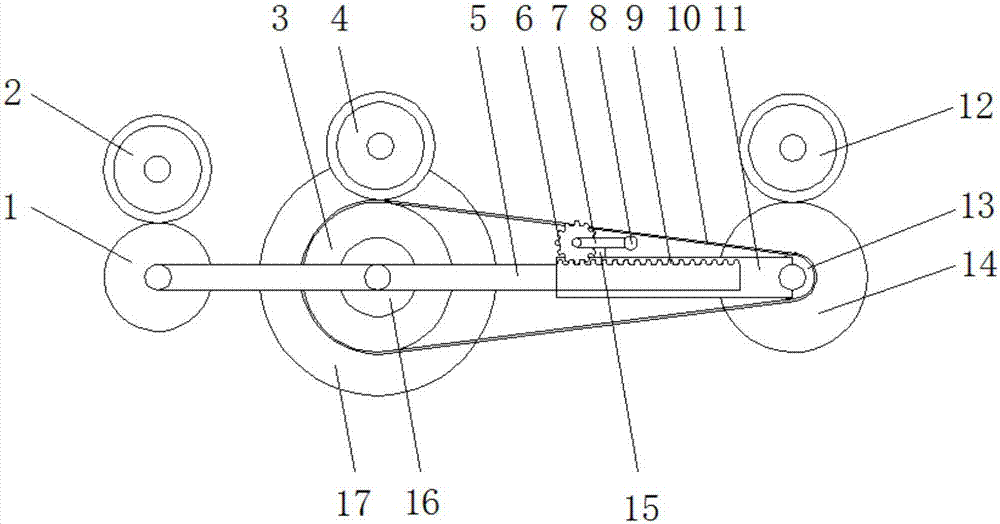
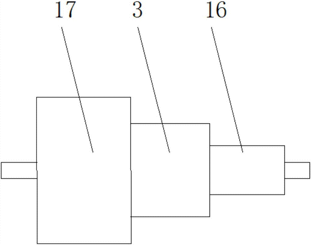
[0014] see Figure 1-2 , the present invention provides a technical solution: a powerful drafting roller for textiles, including a fixed rod 5, one end of the fixed rod 5 is rotatably connected to a lead roller 1, and the top of the lead roller 1 is provided with a lead roller 2, so that The center of the fixed rod 5 is rotatably connected with a feed roller 3, the surface of the feed roller 3 is movably connected with a belt 10, the top of the belt 10 is prov...


PUM


Abstract

The invention discloses a powerful drafting roller for textiles, which comprises a fixed rod, one end of the fixed rod is rotatably connected with a lead roller, the top of the lead roller is provided with a lead roller, and the center of the fixed rod is rotatably connected with a feed roller , the surface of the feeding roller is movably connected with a belt strip, the top of the belt strip is provided with a feeding roller, the other end of the fixed rod is dug with a rack, and the outside of the rack is provided with a sleeve rod, and the sleeve The upper part of the rod is movably connected with a gear, the center of the side surface of the gear is fixedly installed with a connecting rod, the other end of the connecting rod is movably connected with a handle, the other end of the sleeve rod is rotatably connected with a driven wheel, and the other side of the driven wheel is fixed It is connected with a drafting roller, and the upper part of the drafting roller is provided with a drafting top roller. The present invention obtains different mechanical drafting multiples and drafting forces by changing the diameter of the feeding roller, and can be changed at will through the meshing of the gear and the rack. Drafting distance, suitable for drafting of different types of yarns.

Description

technical field [0001] The invention relates to the technical field of textile machinery, in particular to a powerful drafting roller for textile. Background technique [0002] With the development of modern social economy technology and technology, the textile industry has broad prospects for development, which in turn promotes the vigorous development of the textile machinery manufacturing industry. Existing types of textile machinery emerge in endlessly, and the replacement of textile machinery is particularly fast. There are also many kinds of drafting rollers. However, the existing textile drafting rollers have some disadvantages. For example, the mechanical drafting ratio of the existing drafting rollers is generally relatively fixed. When the wire is drafted, the traditional drafting roller cannot change the drafting distance and mechanical drafting multiple at any time, and its adaptability is particularly poor. In this case, the factory can only replace the drafting...

Claims


Application Information

Patent Timeline
Patent Type & Authority Applications(China)
IPC IPC(8): D02J1/22
CPCD02J1/225
Inventor 洪金干杨海波季磊芳
Owner YANCHENG DIJIANI CLOTHING
Why Eureka
Try Eureka