Waste spring stretching and recycling machine

A technology of side plates and transmission wheels, applied in the manufacture of springs from wires, applications, household appliances, etc., can solve the problems of manpower consumption, cumbersome operation process, and low work efficiency, and achieve the goal of improving work efficiency, simple operation, and saving manpower Effect

Active Publication Date: 2021-06-22
乐清市东风弹簧制造有限公司
View PDF6 Cites 0 Cited by
  • Summary
  • Abstract
  • Description
  • Claims
  • Application Information

AI Technical Summary

Problems solved by technology

[0006] In order to overcome the disadvantages of the above-mentioned method, such as cumbersome operation process, low work efficiency, labor-intensive operation, and failure to meet people’s needs, the technical problem to be solved by the present invention is to provide a simple operation that can improve work efficiency. Efficient and manpower-saving waste spring stretching and recycling machine

Method used


Image

  • Waste spring stretching and recycling machine
  • Waste spring stretching and recycling machine
  • Waste spring stretching and recycling machine

Examples


Embodiment 1

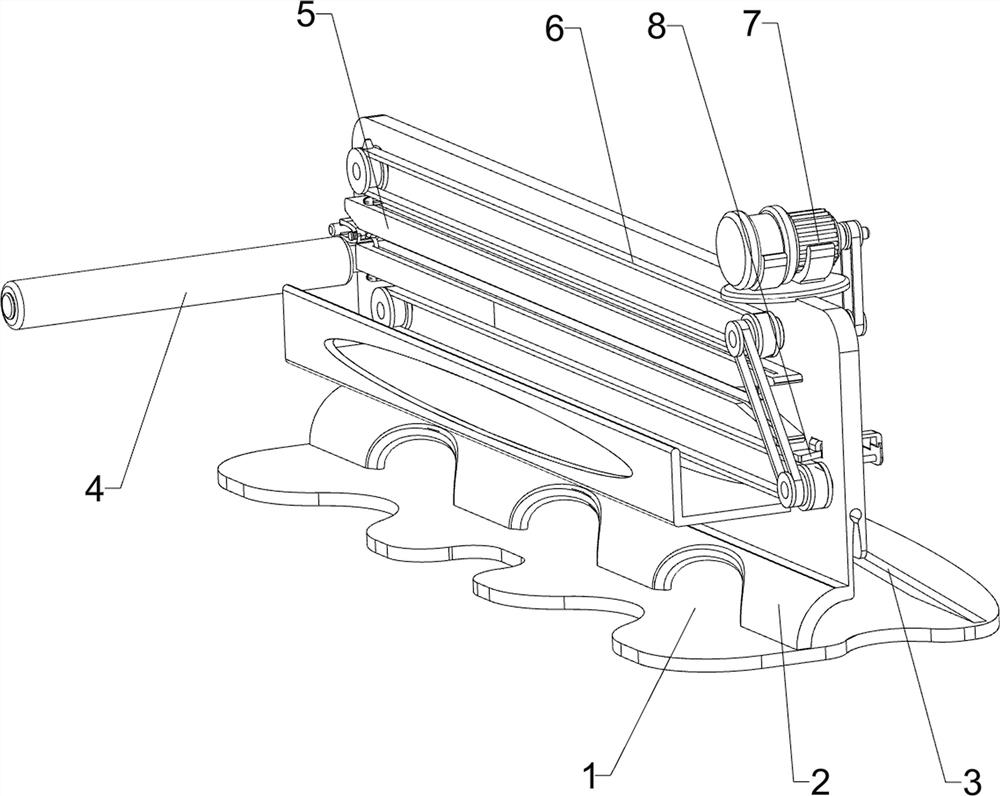
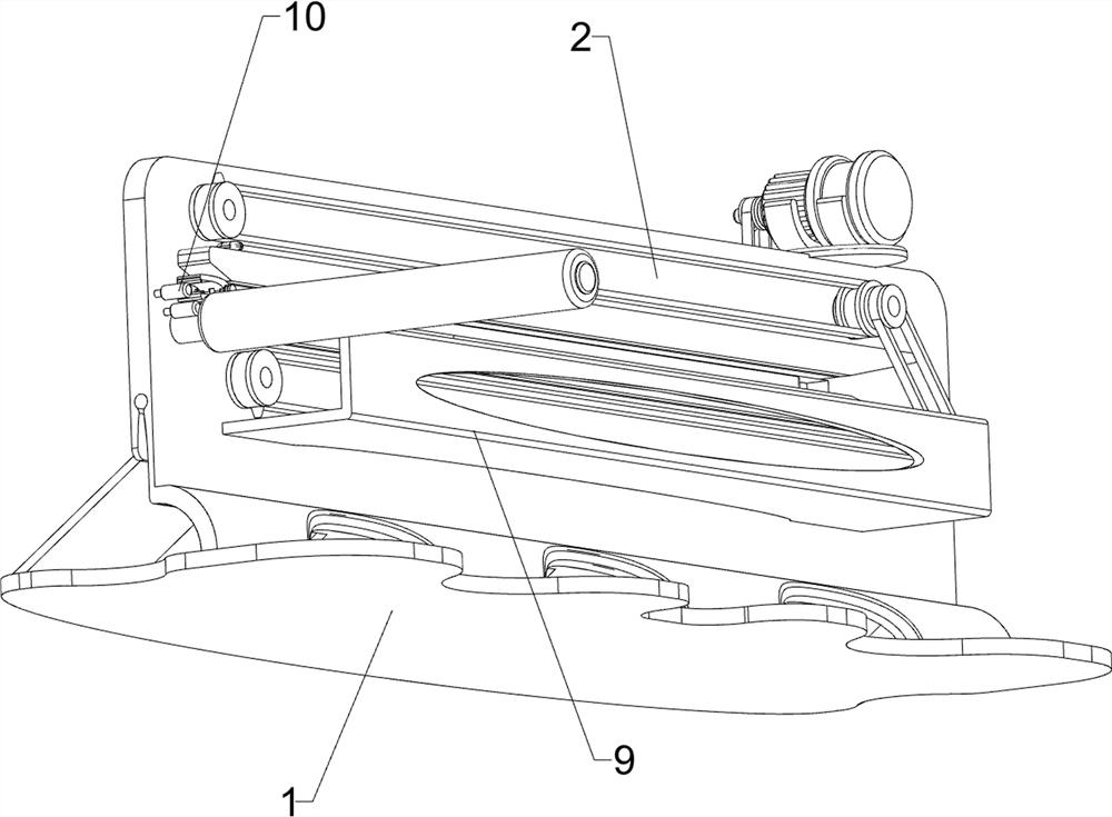
[0026] A waste spring stretching reuse machine, such as Figure 1 to Figure 3 As shown, it includes a mounting plate 1, a side plate 2, a support plate 3 and a roller 4. The top of the mounting plate 1 is connected to the side plate 2, and the support plate 3 is connected between the side plate 2 and the mounting plate 1. The left side of the side plate 2 The side and rear sides are rotatably connected with a roller 4, and also include a clamping device 5, a transmission device 6 and a transmission device 7. The side plate 2 is provided with a clamping device 5, a transmission device 6 and a transmission device 7, and the transmission device 6 It is connected with transmission device 7.

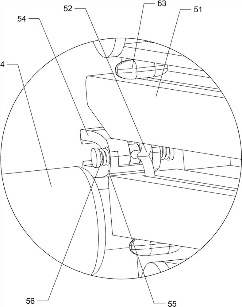
[0027] The clamping device 5 includes a guide plate 51, a connecting rod 52, a slide block 53, an upper clamping plate 54, a lower clamping plate 55 and a torsion spring 56. The left side of the side plate 2 is connected with a guide plate 51 on the upper and lower sides. The connecting rod ...

Embodiment 2

[0032] On the basis of Example 1, such as Figure 4 Shown, also include pushing device 8, and pushing device 8 includes slide bar 81, connecting sleeve plate 82, return spring 83, push plate 84, L-shaped bar 85, cross plate 86, wedge block 87 and guide rod 88, side Both front and rear sides of the right side of the plate 2 are connected with slide bars 81, and a connecting cover plate 82 is slidably connected between the two slide bars 81, and a return spring 83 is connected between the connecting cover plate 82 and the side plate 2, and the connecting cover plate The front and rear sides of the top of 82 are connected with L-shaped rods 85, and a push plate 84 is connected between the L-shaped rods 85 on both sides. Guide rod 88 is slidably matched with connection cover plate 82, and the front side of connection cover plate 82 is connected with cross plate 86, and cross plate 86 is slidably matched with side plate 2, and the left side of cross plate 86 is connected with wedge...


PUM


Abstract

The invention relates to a stretcher, in particular to a waste spring stretching and recycling machine. The technical aim to be achieved by the invention is how to design the waste spring stretching and recycling machine. The machine is simple to operate and capable of improving the working efficiency and saving manpower. In order to achieve the technical aim, the waste spring stretching and recycling machine provided by the invention comprises a mounting plate of which the top is connected with a side plate, a support plate, a rotating roller and a clamping device; the support plate is connected between the side plate and the mounting plate; the rotating roller is rotationally connected to one side of the side plate; and the clamping device is arranged on the side plate. Through cooperative operation of the clamping device, a transmission device and a conveying device, a waste spring is stretched, and therefore the effect of stretching the waste spring is achieved.

Description

technical field [0001] The invention relates to a stretching machine, in particular to a waste spring stretching and reuse machine. Background technique [0002] With the continuous development of modern society and the continuous improvement of people's quality of life, in modern society, spring is a relatively important mechanical part in modern society. Spring is mainly a mechanical part that uses elasticity to work. It is made of elastic materials. The parts are deformed under the action of external force, and then return to their original shape after losing the external force. After the spring is used for a long time, it is easy to cause damage to the spring. The damaged spring can also be recycled. In the process of recycling, it is usually necessary to stretch the spring again. for recycling. [0003] At present, the method of stretching the waste spring is usually by manually pulling the two ends of the waste spring, and then the user stretches the waste spring forc...

Claims


Application Information

Patent Timeline
Patent Type & Authority Applications(China)
IPC IPC(8): B21F35/00B09B3/00
CPCB21F35/00B09B3/00
Inventor 傅明泽
Owner 乐清市东风弹簧制造有限公司
Why Eureka
Try Eureka