
A kind of anti-rotation lifting cylinder

A technology for lifting cylinders and cylinder barrels, applied in the direction of fluid pressure actuating devices, etc., can solve the problems of uneven force on both ends of the piston rod, shorten the service life of the cylinder, and inaccurate control and positioning, so as to achieve simple and reasonable structure and prolong service life Long life, high precision control and positioning effect

Active Publication Date: 2019-04-19
宁波利达气动成套有限公司
View PDF10 Cites 0 Cited by
  • Summary
  • Abstract
  • Description
  • Claims
  • Application Information

AI Technical Summary

Problems solved by technology

[0003] Most of the cylinders in the prior art are rod cylinders. The rod cylinder fixes the cylinder barrel and converts the pressure energy of the compressed air into mechanical energy through the linear reciprocating motion of the piston rod. Due to the high-frequency vibration or tension of the piston rod, it is extremely It is easy to form a broken rod, so the cylinder cannot be used, and the force on both ends of the piston rod is uneven during the movement, resulting in inaccurate control and positioning, and shortening the service life of the cylinder

Method used


Image

  • A kind of anti-rotation lifting cylinder
  • A kind of anti-rotation lifting cylinder
  • A kind of anti-rotation lifting cylinder

Examples


Embodiment Construction

[0021] The present invention will be further described below in conjunction with the accompanying drawings.

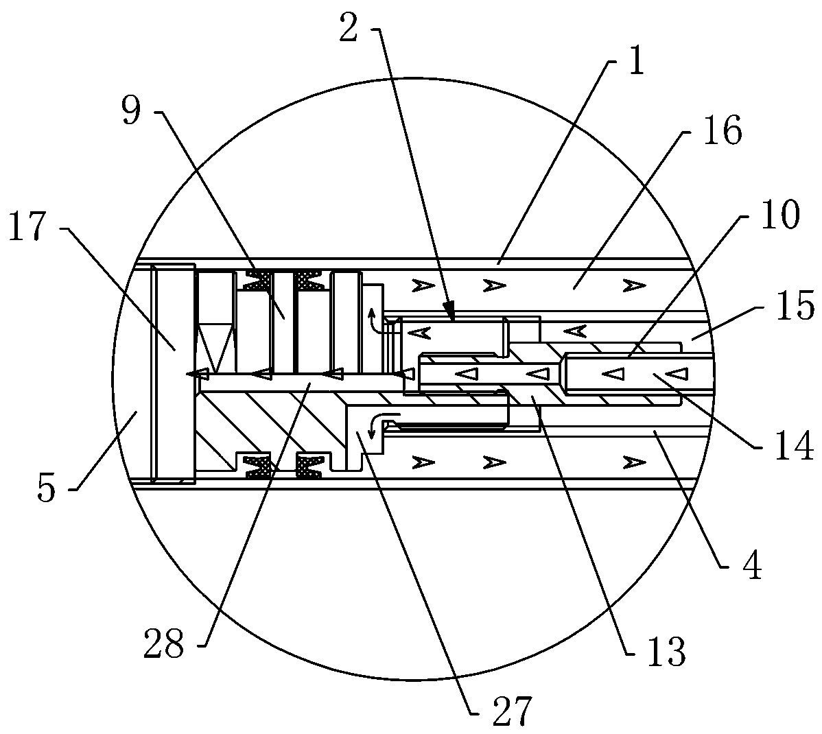
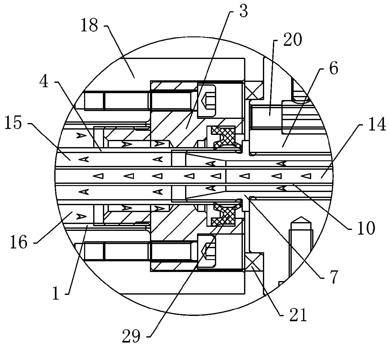
[0022] Such as Figure 1 to Figure 3 As shown, a kind of anti-rotation lifting cylinder described in the present invention comprises a cylinder 1, a piston assembly 2, a piston rod 4, a front cover 5 and a rear cover 3, and the front cover 5 and the rear cover 3 are arranged on the sides of the cylinder 1 respectively. At both ends, the piston rod 4 is arranged in the cylinder barrel 1, the front end of the piston rod 4 is fixedly connected with the piston assembly 2, the piston rod 4 and the rear cover 3 are locked in cooperation, and the mounting seat 6, the end cover 8, and the adapter screw 7 are also included. And the air duct 10, the rear cover 3, the mounting seat 6 and the end cover 8 are fixed in turn, the adapter screw 7 is arranged in the mounting seat 6, the front end of the adapter screw 7 is fixedly connected with the rear end of the piston rod 4, and the...


PUM


Abstract

The invention relates to an anti-rotation lifting cylinder. The anti-rotation lifting cylinder comprises a cylinder barrel, a piston assembly, a piston rod, a front cover and a back cover, and further comprises a mounting seat, an end cover, a connecting screw and an air guide tube, wherein the front cover and the back cover are separately arranged at the two ends of the cylinder barrel; the piston rod is arranged in the cylinder barrel; the front end of the piston rod is fixedly connected with the piston assembly; the piston rod and the back cover are in anti-rotation fit; the back cover, the mounting seat and the end cover are sequentially fixed; the connecting screw is arranged in the mounting seat; the front end of the connecting screw is fixedly connected with the back end of the piston rod; the back end of the connecting screw stretches into the end cover; the piston rod and the connecting screw are hollow; the air guide tube is arranged in the piston rod and the connecting screw in an interpenetrating manner; the front end of the air guide tube is fixedly connected with the piston assembly; and the back end of the air guide tube stretches into the end cover. According to the anti-rotation lifting cylinder, the structure is simple and reasonable, stress is balanced, control and locating precision is high, the piston rod can be prevented from being broken, and the service life of the cylinder is prolonged.

Description

technical field [0001] The invention relates to the technical field of cylinders, in particular to an anti-rotation lifting cylinder. Background technique [0002] The cylinder is a pneumatic component that forms a working volume with the piston. The current cylinder guides the piston to perform linear reciprocating motion, so that the gas in the cylinder is compressed by the piston to increase the pressure, and guides the external executive components to work. [0003] Most of the cylinders in the prior art are rod cylinders. The rod cylinder fixes the cylinder barrel and converts the pressure energy of the compressed air into mechanical energy through the linear reciprocating motion of the piston rod. Due to the high-frequency vibration or tension of the piston rod, it is extremely It is easy to form a broken rod, so the cylinder cannot be used, and the force on both ends of the piston rod is uneven during the movement, resulting in inaccurate control and positioning, and ...

Claims


Application Information

Patent Timeline
Patent Type & Authority Patents(China)
IPC IPC(8): F15B15/14
CPCF15B15/1423F15B15/1433F15B15/1447F15B15/1476
Inventor 夏家永夏国伟龚波明
Owner 宁波利达气动成套有限公司
Learn More